
Product Manual


11
6. Quick Use guide
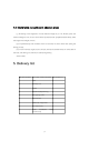
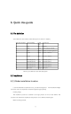
6.1 Pin definition
Stitch definition and interface cable description are shown in Table 5.1.
The serial number
Cable marking
Cable
color
instructions
1
12V
red
positive
2
GND
black
Power supply cathode
3
GND
yellow
Reserve common ground
4
B-/RX
white
TTL RX or 485 B-
5
A+/TX
gray
TTL TX or 485 A+
6
Normally open 1
blue
Normally open 1
7
Normally open 1
green
Normally open 1
8
Normally open 2
brown
Normally open 2
9
Normally open 2
purple
Normally open 2
10
The input
orange
The input
Table 5.1 Pin definition and cable description
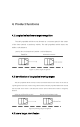
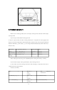
6.2 installation
6.2.1 Radar installation location
It is recommended to install from 0.5 to 1.0m above the ground. If the installation height
is less than 0.5m, the installation should be adjusted appropriately
Pitching Angle;
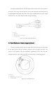
The installation position is attached to the logo position in front of the vehicle. The
customer can reserve the installation hole position or for different vehicle types
Make mounting bracket.