ITS - A08 type FCW Forward Collision Warning System Product Manual V3.0 2020.3.14 Microbrain Intelligent Technology Co., Ltd.
Disclaimer Welcome to buy this product. The ratio of changsha's intelligent technology co., LTD. Website https://www.microbrain.com.cn/. Please read this statement carefully before using this product. Once used, it shall be deemed to be an approval and acceptance of the contents of this statement. Please install and use the product in strict accordance with the manual. In case of any damage or damage caused by improper use, Changsha Mozhibi Intelligent Technology Co., Ltd.
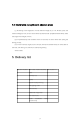
Version history The date of version Version described 2019.07.31 1.0 Initializing creation 2019.11.21 2.0 Normal iteration 2020.3.14 3.
directory 1、A list .................................................................................................................................................................. 5 2. Product features .............................................................................................................................................. 6 3. Product parameters ....................................................................................................................................... 7 4.
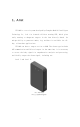
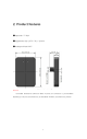
1、A list ITS-A08 is a set of system developed by Changsha Mozhibi Intelligent Technology Co., Ltd. for forward collision warning FCW, which gives early warning to dangerous targets in the lane directly ahead. Its unique ability to penetrate smoke, fog, and dust is available for allday, all-weather applications. ITS-A08 can detect targets as far as 80M. The alarm type includes 485 communication and IO level output.
2. Product features ⚫ spectrum: 77-81G ⚫ appearance size: 107.5 * 73.2 * 18 mm ⚫ waterproof level: IP67 FIG. 2.1 Dimension drawing Remark: Unmarked dimensional tolerance: When ≤10mm, the tolerance is ±0.3mm;When between (10~50) mm, the tolerance is ±0.5mm;When ≥50mm, the tolerance is ±0.8mm.
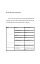
3. Product parameters The ITS-A08 radar adopts the FMCW modulation mode with high complexity, and is accurate in the measurement range determine the coordinates and velocity of the target relative to the radar. Table 3.1 ItS-A08 Performance parameters features System property Detection performance Communication interface parameter Technical indicators Working voltage 9-24V Working temperature - 40 ℃ ~ 85 ℃ Power consumption < 2.5 W.
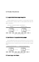
4. Product functions 4.1 Longitudinal stationary target recognition The self-propelled vehicle moves forward at a constant speed in the center of the lane towards a stationary vehicle. The self-propelled vehicle starts one within a safe distance Level 2 alert. Activate level 2 within a critical distance. Figure 4.1 Static target recognition 4.
The self-propelled vehicle and the target vehicle travel at the same speed in the center of the lane, and the vehicle in front of the adjacent lane slows down to a speed significantly lower than that of the self-propelled vehicle and the target vehicle in front; No alarm will be issued during overtaking. Figure 4.3 Lateral target identification 4.
4.5 Interference recognition in adjacent areas (1) According to the regulation of road clearance height in 2.0.7 of JTG B01-2014, the clearance height is 4.5m, and no alarm will be issued if the self-propelled vehicle drives under the target with a height of 4.
6. Quick Use guide 6.1 Pin definition Stitch definition and interface cable description are shown in Table 5.1.
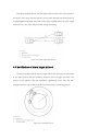
FIG. 6.2 Radar installation diagram 6.3 Output Agreement Radar has two warning modes, one is IO output warning mode, the other is 485 output warning mode. IO port output mode Radar warning protocol: In IO port output mode, the radar warning information is composed of warning lights and buzzers, and the warning level is determined by TTC (collision time, unit second) and absolute distance threshold L1 (unit meter). L1 is the range threshold detected by radar.
T < = TTC and L < L1 Data protocol Level 2 warning AA BB FA 02 XX XX 00 00 00 FE FA 00 CC head Y=0xAABB V=0xCCDD alarm level Distance =(y- The The tail 32768)/10 speed =(V-32768)/10 unit: m, step: 0.
Radar warning output 88 A mode A=0x00 A=0x01 IO port 08 A output 485 output 88 A Note: After setting, ID0x201 and data: 0x7f 0x00 need to be sent to the radar. To save the Settings. 6.3.2 Radar boot self-test The radar will conduct self-check at startup. If the radar output mode is IO port output mode, the buzzer and the early-warning light will work twice at the same time at startup.
7.
Federal Communications Commission (FCC) Interference Statement This equipment has been tested and found to comply with the limits for a Class B digital device, pursuant to Part15 of the FCC Rules. These limits are designed to provide reasonable protection against harmful interference in a residential installation. This equipment generate, uses and can radiate radio frequency energy and, if not installed and used in accordance with the instructions, may cause harmful interference to radio communications.