
User Manual

REV 13502-20161123 6
13502 ENGLISH
ASSEMBLY
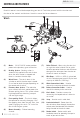
Assembling the Winch
This CPE 3000 lb. (1361 kg.) winch is designed
with a bolt pattern that is standard in this class
of winch. Many winch mounting kits are available
that utilize this bolt pattern for the most popular
UTVs and ATVs. If you cannot find a kit locally,
contact CPE and we will provide you with the
name of a dealer.
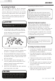
1. Insert M10x20 bolts through the mounting
channel holes and attach the roller fairlead
to the mounting channel with the M10 lock
washers and M10 nuts provided.
2. Turn the winch upside down. Place the
mounting channel on the winch, making sure
the winch is centered in the middle of it.
3. Thread the M8x25 bolts through the M8 flat
and lockers washers, and then thread through
the mounting channel. Tighten the bolts. DO
NOT over tighten.
4. Turn winch right side up. Disengage the
clutch by moving the Cam Ring to the “Out”
position. Release the wire rope and pull
through the roller fairlead.
5. Attach the clevis hook to the cable, and then
hand strap to the clevis hook.
The type of vehicle to which the winch and
mounting channel will be applied, will dictate
the type of mounting kit that should be used
(Speed Mount™ Hitch Adapter, Standard
Mounting Channel, or Specialty Mounting Kit).
NOTE
If utilizing a mounting plate, ensure that the three
major sections (motor, drum and gear housing) are
properly aligned. Proper alignment of the winch will
allow for even distribution of the full rated load.
CAUTION
Mounting bolts must be SAE grade 5 or better
and torque to 34 ft. lbs.
CAUTION
Assembling the Winch Cont’d.
Contactor/Solenoid Location
Find a location for the contactor/solenoid. It is
recommended that the contactor/solenoid be
mounted close to the battery in a clean, dry
location. Make sure the location chosen allows for
sufficient clearance from all metal components.
Drill mounting holes if required. Once a location
is found, DO NOT install the unit until all wiring
is completed (see wiring section).
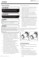
Installing the Rocker Switch
1. Decide which handlebar the rocker switch will
be mounted on. (The rocker switch is usually
installed on the left handlebar).
2. Use a piece of electrical tape (not provided)
around the handlebar to help prevent rotation
of the mount.
3. Tighten the rocker switch in place. DO NOT
over tighten or tighten/clamp over any hoses
or cables.
4. Once the rocker switch is mounted, the wires
can be routed back to where the contactor/
solenoid is located.
5. Make sure the handlebars have full range of
motion and then secure the rocker switch’s
cable with the supplied cable ties.
Terminals coming in contact with metal will cause
a direct short, possibly causing contactor/solenoid
and/or battery damage.
NOTE