
Door User Manual

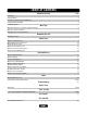
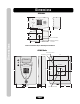
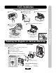
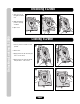
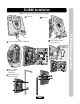
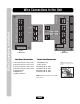
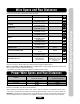
Table Of Contents
- Installation Manual for EL Models
- Table of Contents
- Dimensions
- EL25 Installation
- Rotating the Keypad for Vertical Mounting
- Unlocking EL2000
- Locking EL2000
- EL2000 Installation
- Wire Connections to the Unit
- Wire Specs and Run Distances
- Power Wire Specs and Run Distances
- Grounding the Units
- Wiring 1 Unit to Telco Line
- Wiring Multiple Units to Telco Line
- Wiring with No Telco Line
- Wiring to Dedicated Telco Line
- Wiring to an Internal Phone System
- Connection To An NPBI System
- Wiring a Door Strike Lock
- Wiring a Maglock
- Wiring a Gate Operator
- Wiring a Key Switch/PIR/REX
- Wiring a Door Sensing Device
- Wiring the AutoCall Feature
- Wiring a Radio Frequency Module
- Wiegand Card Reader/Keypad
- Wiring a Postal Lock Switch - EL25 Models Only
- Wiring an Internal Camera [CCTV]
- Wiring Power to the Unit
- Powering Up and Checking the LEDs
- Troubleshooting
- Repair Parts
- Your System Diagram
- Your Wiring Configuration
- Accessories
- FCC and DOC Requirements

Page 7
Wire Specs and Run Distances
Wire Specs and Run Distances
Use this chart to pull wires in preparation of your installation:
Power Wire Specs and Run Distances
Description of Wire Run
Grounding the Chassis
Residence and Telco Phone Lines
Door Strike
Magnetic Lock
Dry Contact Closure (Most Gate Operators)
Exit Request (REX) / Auxiliary Open Devices
AutoCall
Door Status Sensor
Barium Ferrite and Wiegand Readers
Proximity Readers
Radio Frequency Module (RF)
Postal Lock
CCTV Camera (Optional)
Wire Specification
12 AWG Copper
2 Twisted Pairs
18-24 AWG Shielded
2-Conductor
18-22 AWG Shielded
2-Conductor
18-22 AWG Shielded
2-Conductor
18-24 AWG Shielded
2-Conductor
18-24 AWG Shielded
2-Conductor
18-24 AWG Shielded
2-Conductor
18-24 AWG Shielded
5-Conductor
18-24 AWG Shielded
5-Conductor
22 AWG Shielded
RG-6 Coaxial
75 ohm
2-Conductor
18-24 AWG Shielded
Single Conductor
RG-59u Coaxial
Maximum Distance
12 feet
5000 feet*
500 feet
500 feet
100 feet
1000 feet
(Monitor with a .25 volt
p-p composite signal
sensitivity)
Page
8
9-14
15
15
16
16
17
17
18
18
18
19
19
NOTE: Use metal conduit - run wires in metal conduit instead of PVC pipe. Wires run in PVC conduit may
experience interference. Metal conduits also add extra protection against lightning strikes.
Never run Telco Wires and High Voltage wires in the same conduit. The high voltage may interfere with the Telco
Wires, possibly causing the system to malfunction.
* Total distance from Telco to residence regardless of number of units in chain.
Distance
Under 30 Feet
30 - 75 Feet
75 - 250 Feet
12 VAC Power (Included)
2-Conductor Shielded
14 AWG
14 AWG
14 AWG
12 VDC Power (Not Provided)
2-Conductor Shielded
14 AWG
14 AWG
N/A
Always provide power from a dedicated source. Plug provided transformer into an outlet wired to its own 10 AMP
minimum circuit breaker. This will prevent two problems:
• Other equipment cannot introduce spikes, noise, surges or dips into the power circuit that will affect the system.
• The system’s operation will not be affected if any other equipment develops a short circuit across the power line.
CAUTION: Not responsible for conflicts between the information listed in the above table and the requirements of
your local building codes. The information is for suggested use only. Check your local codes before installation.