
Door User Manual

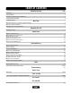
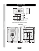
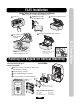
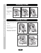
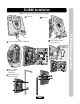
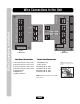
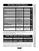
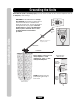
Table Of Contents
- Installation Manual for EL Models
- Table of Contents
- Dimensions
- EL25 Installation
- Rotating the Keypad for Vertical Mounting
- Unlocking EL2000
- Locking EL2000
- EL2000 Installation
- Wire Connections to the Unit
- Wire Specs and Run Distances
- Power Wire Specs and Run Distances
- Grounding the Units
- Wiring 1 Unit to Telco Line
- Wiring Multiple Units to Telco Line
- Wiring with No Telco Line
- Wiring to Dedicated Telco Line
- Wiring to an Internal Phone System
- Connection To An NPBI System
- Wiring a Door Strike Lock
- Wiring a Maglock
- Wiring a Gate Operator
- Wiring a Key Switch/PIR/REX
- Wiring a Door Sensing Device
- Wiring the AutoCall Feature
- Wiring a Radio Frequency Module
- Wiegand Card Reader/Keypad
- Wiring a Postal Lock Switch - EL25 Models Only
- Wiring an Internal Camera [CCTV]
- Wiring Power to the Unit
- Powering Up and Checking the LEDs
- Troubleshooting
- Repair Parts
- Your System Diagram
- Your Wiring Configuration
- Accessories
- FCC and DOC Requirements

Page 6
Wire Connections to the Unit
Input Board Connections
1. Door 1 Exit Request and Door Status
2. Door 2 Exit Request and Door Status
3. Door 3 Exit Request and Door Status
4. Door 4 Exit Request and Door Status
5. Postal Lock Input
6. AutoCall Input
7. Power 12 VAC Input
Output Board Connections
8. Resident Tip/Ring
9. Telco Tip/Ring
10. Relay 4, NO, NC, COM
11. Relay 3, NO, NC, COM
12. Relay 2, NO, NC, COM
13. Relay 1, NO, NC, COM
NOTE: All relays are factory set to “Strike”
and “10 sec.”
DO NOT overload the removable
terminal block connectors. One wire
per hole.
20-Pin
to Main Board
14-Pin
to Main Board
IO Output Board
IO Input Board
J2
J3
LED 2
LED 1
RELAY 1
RELAY 2
RELAY 3
RELAY 4
8
9
DOOR
STAT 4
EXIT
REQ 4
COM
4
3
2
1
5
6
7
10
11
12
13
DOOR
STAT 3
EXIT
REQ 3
COM
DOOR
STAT 4
EXIT
REQ 2
COM
DOOR
STAT 1
EXIT
REQ 1
COM
J5
J7
J6
J4
POSTAL
AUTO
J1
POWER
12VAC/DC
J3
J5
J4
J1
NO
NC
C
NO
NC
C
NO
NC
C
NO
NC
C
LED 4
LED 3
RES
TELCO
J6
J8
Wire Connections to the Unit