
Door User Manual
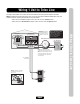
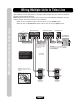
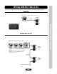
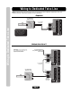
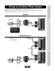
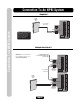
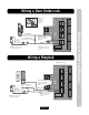
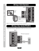
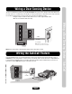
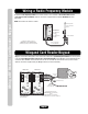
Table Of Contents
- Installation Manual for EL Models
- Table of Contents
- Dimensions
- EL25 Installation
- Rotating the Keypad for Vertical Mounting
- Unlocking EL2000
- Locking EL2000
- EL2000 Installation
- Wire Connections to the Unit
- Wire Specs and Run Distances
- Power Wire Specs and Run Distances
- Grounding the Units
- Wiring 1 Unit to Telco Line
- Wiring Multiple Units to Telco Line
- Wiring with No Telco Line
- Wiring to Dedicated Telco Line
- Wiring to an Internal Phone System
- Connection To An NPBI System
- Wiring a Door Strike Lock
- Wiring a Maglock
- Wiring a Gate Operator
- Wiring a Key Switch/PIR/REX
- Wiring a Door Sensing Device
- Wiring the AutoCall Feature
- Wiring a Radio Frequency Module
- Wiegand Card Reader/Keypad
- Wiring a Postal Lock Switch - EL25 Models Only
- Wiring an Internal Camera [CCTV]
- Wiring Power to the Unit
- Powering Up and Checking the LEDs
- Troubleshooting
- Repair Parts
- Your System Diagram
- Your Wiring Configuration
- Accessories
- FCC and DOC Requirements

Page 18
Wiring a RF Module / Card Reader / Keypad
Wiring a Radio Frequency Module
An optional radio frequency module and a remote antenna can be installed if the residents will access a
controlled area with a transmitter. Refer to instructions supplied with the optional RF Module for more
information.
Wiegand Card Reader/Keypad
Wiegand card readers and keypads can be connected to either of 2 optional Wiegand modules that can be placed
in the unit. Each Wiegand module supports two card readers/keypads. Some Wiegand card reader/keypads have
a sixth blue wire. DO NOT connect this blue wire to the unit. Insulate this wire from the unit to prevent a short
(Refer to instructions supplied with your Wiegand device for more information).
RG-6
Coaxial
Connector
RG-6 Coaxial Cable
100 Feet Maximum
Remote Antenna
Avoid any metallic
surface around the
antenna.
RF Module(s) will fit in positions
J400 (Device 1) and/or J407 (Device 3)
(4 Mounting Screws per Board are Required)
1 RF Module Kit
Part # RFMODKT
(390 MHz)
or
Part # RFMODKT3
(315 MHz)
J407 Position J400 Position
Card Reader is Wired to Device 1
P12V
P5V
DATA 0
DATA 1
LED
COM P12V
P5V
DATA 0
DATA 1
LED
COM
J1J2 J1J2
Device 1Device 3 Device 2Device 4
Red Power
Green
White
Brown
Black
Shield
(Attach to the
unit ground only).
Blue (Insulate this wire).
Use 18-24
AWG
1 Wiegand Module Kit
Part # WOMODKT
P12V
P5V
DATA 0
DATA 1
LED
COM P12V
P5V
DATA 0
DATA 1
LED
COM
Wiegand Modules will fit in
J400 as Device 1 (J1) and 2 (J2)
and/or
J407 as Device 3 (J1) and 4 (J2)
(4 Mounting Screws per Board are Required)
NOTE: The remote can control 1-4 doors.