
Door User Manual
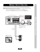
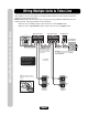
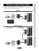
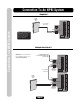
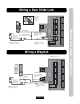
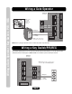
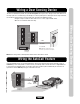
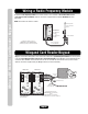
Table Of Contents
- Installation Manual for EL Models
- Table of Contents
- Dimensions
- EL25 Installation
- Rotating the Keypad for Vertical Mounting
- Unlocking EL2000
- Locking EL2000
- EL2000 Installation
- Wire Connections to the Unit
- Wire Specs and Run Distances
- Power Wire Specs and Run Distances
- Grounding the Units
- Wiring 1 Unit to Telco Line
- Wiring Multiple Units to Telco Line
- Wiring with No Telco Line
- Wiring to Dedicated Telco Line
- Wiring to an Internal Phone System
- Connection To An NPBI System
- Wiring a Door Strike Lock
- Wiring a Maglock
- Wiring a Gate Operator
- Wiring a Key Switch/PIR/REX
- Wiring a Door Sensing Device
- Wiring the AutoCall Feature
- Wiring a Radio Frequency Module
- Wiegand Card Reader/Keypad
- Wiring a Postal Lock Switch - EL25 Models Only
- Wiring an Internal Camera [CCTV]
- Wiring Power to the Unit
- Powering Up and Checking the LEDs
- Troubleshooting
- Repair Parts
- Your System Diagram
- Your Wiring Configuration
- Accessories
- FCC and DOC Requirements

Page 13
Wiring to an Internal Phone System
Wiring to an Internal Phone System
The units can be wired to any Analog Trunk in an internal home phone system.
NOTE: Installation where fiber optic phone lines are present may require additional modifications from your
telephone provider. Contact your provider for more information.
IO Output Board
LED 2
LED 1
RELAY 1
RELAY 2
RELAY 3
RELAY 4
J3
J5
J4
J1
NO
NC
C
NO
NC
C
NO
NC
C
NO
NC
C
LED 4
LED 3
RES
TELCO
J6
J8
Tip
Ring
Use 18-24 AWG
2 twisted pair
Analog
Trunk
Telco Entrance Box
Demarcation Point
Internal
Phone System
Ring
Tip
EX 1 EX 3Analog EX 4 2
T
R
Tip
Ring
Never run Telco wires and High
Voltage wires in the same
conduit. The high voltage wires
may interfere with the Telco
wires, possibly causing the
system to malfunction.
Single Unit
Multiple Units (Up to 7)
IO Output Board
LED 2
LED 1
RELAY 1
RELAY 2
RELAY 3
RELAY 4
J3
J5
J4
J1
NO
NC
C
NO
NC
C
NO
NC
C
NO
NC
C
LED 4
LED 3
RES
TELCO
J6
J8
Tip
Ring
Tip
Ring
IO Output Board
LED 2
LED 1
RELAY 1
RELAY 2
RELAY 3
RELAY 4
J3
J5
J4
J1
NO
NC
C
NO
NC
C
NO
NC
C
NO
NC
C
LED 4
LED 3
RES
TELCO
J6
J8
Tip
Ring
Tip
Ring
Use 18-24 AWG
2 twisted pair
IMPORTANT: You must program the unit
ID's for each unit wired in the series. See
Keypad Programming Manual.
Unit ID 6
Output Board
(See page 6)
Unit ID 7
Output Board
(See page 6)
To next unit (Unit ID 5 then
4 etc.) (Unit ID 1 is farthest away
from Telco Box)
Analog
Trunk
Telco Entrance Box
Demarcation Point
Internal
Phone System
Ring
Tip
EX 1 EX 3Analog EX 4 2
T
R
Tip
Ring