
User Manual
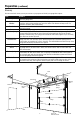
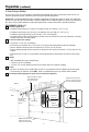
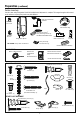
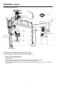

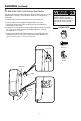
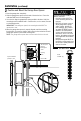
Table Of Contents
- Wall Mount Garage Door Opener Model RJO20
- Table of Contents
- Preparation
- Installation
- 1 Attach the Collar to the Garage Door Opener
- 2 Position and Mount the Garage Door Opener
- 3 Attach the Emergency Release Rope and Handle
- 4 Power Door Lock Location
- 5 Install Power Door Lock
- 6 Position the Cable Tension Monitor (Required)
- 7 Attach the Cable Tension Monitor (Required)
- 8 Install the Door Control (myQ Control Panel)
- 9 Install Remote Light
- 10 Install the Protector System®
- 11 Connect Power
- 12 Align the safety reversing sensors
- Adjustment
- Operation
- Programming
- Getting Connected
- Maintenance
- Troubleshooting
- Automatic Garage Door OpenerSafety & Maintenance Guide
- Accessories
- Warranty
- Repair Parts
- Contact Information

6
TOP
DRILL 5/16"
DRILL 3/4"
DRILL 5/16"
132A2505
Remote Control Visor Clip
3-Button Premium Remote
Control Model 953ESTD (1)
Remote Light
with Hardware Bag
Power Door Lock with
Wire and Connector
Chamberlain
Internet Gateway
White & White/Red Wire
Garage Door Opener
Cable Tension Monitor
with Wire
Mounting
Bracket
Collar with
Set Screws
Safety Reversing
Sensor Bracket (2)
The Protector System
®
Safety Reversing Sensors (2)
with White & White/Black Wire
Lock
Template
Carton Inventory
Save the carton and packing material until the installation and adjustment is complete. The images throughout this manual
are for reference only and your product may look different.
Door Control
(myQ Control
Panel)
Model 041A7928-3
NOT SHOWN: Safety labels and literature
Preparation (continued)
Screw
#10-32 (2)
REMOTE LIGHT HARDWARE
INCLUDED HARDWARE
ACCESSORIES
Screw
14-10x2" (4)
Screw
1/4"-20x1/2" (2)
Screw
#8-32x1" (2)
Drywall Anchor (screw-in) (2)
Screw 6ABx1-1/4"
(Standard installation) (2)
Screw 6-32x1"
(pre-wired) (2)
Drywall
Anchors (2)
Rope
Handle
Wing Nut
1/4"-20 (2)
Carriage Bolt
1/4"-20x1/2" (2)
Drywall Anchor (screw-in) (2)
Screw #4-20x7/16" (2)
Hinge clip (1)
Latch clip (1)
Screw #6x1" (2)