Installation and operating instructions for rolling door opener Model RDO800-series Chamberlain GmbH Alfred-Nobel-Strasse 4 66793 Saarwellingen Germany TEL: +49 (0) 6838/907-250 FAX: +49 (0) 6838/907-179 www.liftmaster.
Start by Reading These Important Safety Instructions WARNING: Failure to comply with the following instructions may result in serious personal injury or property damage. • Read these instructions carefully and follow ALL instructions carefully • The garage door opener is designed and tested to offer reasonable safe service provided it is installed and operated in strict accordance with the instructions in this manual.
Door Requirements The maximum allowable door height is 4.5m, maximum allowable curtain area is 12.0m² (door height in metres multiplied by the width in metres) and maximum allowable door weight is 100kg. The Protector System™ (Safety Beams) must be installed if the force at the edge of the closing door force exceeds 400N (40kgf). Door shaft diameter must not exceed 35mm.
5 Prepare Opener Set Opener Position (Left or Right hand) For left hand side installations the wire jumper should be removed. For right hand side installations the wire jumper should be in place (factory installed). Attaching the Extension Poles (if required) 1. Insert the extension poles into the gear 2. Align the extension pole holes with the gear holes 3. Using the supplied screws secure the extension poles. Place the Opener in Manual Release mode.
6 Installation steps FOR RIGHT HAND INSTALLATIONS (REFER SECTION 5, page 3) 1. Ensure that the opener position jumper (wire connector) is in place (refer section 5, page 3). 2. Place the opener in manual release mode (refer section 5, page 3). 3. Open the roller door fully. For safety, tie a rope around the door. 4. Ensure that the U-bolt on the left hand side of the door is secure. 5. Mark the position of the door shaft on the right hand door bracket. 6.
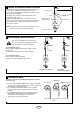
7 Attach the Release Handle and Cord • Thread one end of the rope through the hole in the top of the red handle so “NOTICE” reads right side up as shown. Secure with an overhand knot at least 25mm from the end of the rope to prevent slipping. • Thread the other end of the rope through the link on the emergency release cable. • Adjust rope length so the handle is no higher than 1.8m above the floor. Secure with an overhand knot. If the door is greater than 2.
10 Program your Opener & Remote Please note your remote controls and wall plate have already been programmed into your operator. Activate the opener only when door is in full view, free of obstruction and properly adjusted. No one should enter or leave garage while door is in motion. Do not allow children to operate push button(s) or remote(s). Do not allow children to play near the door.
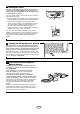
12 Setting the Force The force, as measured on the closing edge of the door, should not exceed 400N (40kgf). If the closing force is measured to more than 400N, the Protector System must be installed. See section 14. The force setting regulates the amount of power required to open and close the door. 1. Press the purple button (1) twice to enter opener into Force Adjustment Mode. The indicator light (2) will flash quickly. 2. Press the green start button (4) on the bottom of the opener.
15 Special Features 2 1 1.Motion Detecting Control Panel Connect white/red wire to the red quick connect terminal and the white wire to the white quick connect terminal. 3 LOCK LIGHT 2.The Protector System™ (Safety Beams) Connect both white wires to the white quick connect terminal and both white/black wires to the grey quick connect terminal. 0 180 sec. 5 50 3.Flashing light connection. The flashing light can be installed anywhere. 4.
Troubleshooting 1. The opener doesn't operate from either the green start button or the remote controls: • Does the opener have electric power? Plug a lamp into the outlet. If it doesn't light, check the fuse box. • Have you disabled all door locks? Review installation instruction warnings on page 1. • Is there a build-up of ice or snow under the door? The door may be frozen to the ground. Remove any restriction. • The garage door spring may be broken. Have it replaced. 2.
MAINTENANCE OF YOUR OPENER SPECIFICATIONS Once a Month: Input Voltage: 230-240VAC, 50Hz, 90W • Repeat safety reverse test. Make any necessary adjustments. Rated Load: 18Nm Max.Pull Force: 550N Max. Door Weight 100kg Idle Current: less than 25mA @ 230VAC Drive: DC gearmotor permanent lubrication OPERATION OF YOUR OPENER Max. Drum Rotations: 5 Your opener can be activated by any of the following devices: Memory Registers: 64 Operating Frequency: 433.92MHz • Manually operate door.
GARAGE DOOR OPENER WARRANTY Declaration of Conformity Chamberlain warrants to the first retail purchaser of this product that the product shall be free from any defect in materials and/or workmanship for a period of 24 full months (2 years) from the date of purchase. Upon receipt of the product, the first retail purchaser is under obligation to check the product for any visible defects.
Installation and operating instructions for rolling door opener Model RDO800GB Chamberlain GmbH Alfred-Nobel-Strasse 4 66793 Saarwellingen Germany TEL: +49 (0) 6838/907-250 FAX: +49 (0) 6838/907-179 www.liftmaster.
Start by Reading These Important Safety Instructions WARNING: Failure to comply with the following instructions may result in serious personal injury or property damage. • Read these instructions carefully and follow ALL instructions carefully • The garage door opener is designed and tested to offer reasonable safe service provided it is installed and operated in strict accordance with the instructions in this manual.
3 Door Requirements The maximum allowable door height is 4.5m, maximum allowable curtain area is 12.0m² (door height in metres multiplied by the width in metres) and maximum allowable door weight is 100kg. The Protector System™ (Safety Beams) must be installed if the force at the edge of the closing door force exceeds 400N (40kgf). Door shaft diameter must not exceed 35mm.
5 Prepare Opener Set Opener Position (Left or Right hand) For left hand side installations the wire jumper should be removed. For right hand side installations the wire jumper should be in place (factory installed). Attaching the Extension Poles (if required) 1. Insert the extension poles into the gear 2. Align the extension pole holes with the gear holes 3. Using the supplied screws secure the extension poles. Place the Opener in Manual Release mode.
6 Installation steps FOR RIGHT HAND INSTALLATIONS (REFER SECTION 5, page 3) 1. Ensure that the opener position jumper (wire connector) is in place (refer section 5, page 3). 2. Place the opener in manual release mode (refer section 5, page 3). 3. Open the roller door fully. For safety, tie a rope around the door. 4. Ensure that the U-bolt on the left hand side of the door is secure. 5. Mark the position of the door shaft on the right hand door bracket. 6.
7 Attach the Release Handle and Cord • Thread one end of the rope through the hole in the top of the red handle so “NOTICE” reads right side up as shown. Secure with an overhand knot at least 25mm from the end of the rope to prevent slipping. • Thread the other end of the rope through the link on the emergency release cable. • Adjust rope length so the handle is no higher than 1.8m above the floor. Secure with an overhand knot. If the door is greater than 2.
10 Program your Opener & Remote Please note your remote controls and wall plate have already been programmed into your operator. Activate the opener only when door is in full view, free of obstruction and properly adjusted. No one should enter or leave garage while door is in motion. Do not allow children to operate push button(s) or remote(s). Do not allow children to play near the door.
12 Setting the Force The force, as measured on the closing edge of the door, should not exceed 400N (40kgf). If the closing force is measured to more than 400N, the Protector System must be installed. See section 14. The force setting regulates the amount of power required to open and close the door. 1. Press the purple button (1) twice to enter opener into Force Adjustment Mode. The indicator light (2) will flash quickly. 2. Press the green start button (4) on the bottom of the opener.
15 Special Features 2 1 1.Motion Detecting Control Panel Connect white/red wire to the red quick connect terminal and the white wire to the white quick connect terminal. 3 LOCK LIGHT 2.The Protector System™ (Safety Beams) Connect both white wires to the white quick connect terminal and both white/black wires to the grey quick connect terminal. 0 180 sec. 5 50 3.Flashing light connection. The flashing light can be installed anywhere. 4.
Troubleshooting 1. The opener doesn't operate from either the green start button or the remote controls: • Does the opener have electric power? Plug a lamp into the outlet. If it doesn't light, check the fuse box. • Have you disabled all door locks? Review installation instruction warnings on page 1. • Is there a build-up of ice or snow under the door? The door may be frozen to the ground. Remove any restriction. • The garage door spring may be broken. Have it replaced. 2.
MAINTENANCE OF YOUR OPENER SPECIFICATIONS Once a Month: Input Voltage: 230-240VAC, 50Hz, 90W • Repeat safety reverse test. Make any necessary adjustments. Rated Load: 18Nm Max.Pull Force: 550N Max. Door Weight 100kg Idle Current: less than 25mA @ 230VAC Drive: DC gearmotor permanent lubrication OPERATION OF YOUR OPENER Max. Drum Rotations: 5 Your opener can be activated by any of the following devices: Memory Registers: 64 Operating Frequency: 433.92MHz • Manually operate door.
GARAGE DOOR OPENER WARRANTY Declaration of Conformity Chamberlain warrants to the first retail purchaser of this product that the product shall be free from any defect in materials and/or workmanship for a period of 24 full months (2 years) from the date of purchase. Upon receipt of the product, the first retail purchaser is under obligation to check the product for any visible defects.