
User Guide
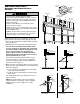


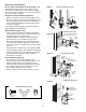


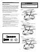
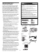
Table Of Contents
- Model PD432D 1/2 HP
- TABLE OF CONTENTS
- INTRODUCTION
- ASSEMBLY
- INSTALLATION
- STEP 1 Determine the Header Bracket Location
- STEP 2 Install the Header Bracket
- STEP 3 Attach the Rail to the Header Bracket
- STEP 4 Install The Protector System®
- STEP 5 Position the Opener
- STEP 6 Hang the Opener
- STEP 7 Install the Door Control
- STEP 8 Install the Lights
- STEP 9 Attach the Emergency Release Rope and Handle
- STEP 10 Electrical Requirements
- STEP 11 Complete the Safety Reversing Sensor Installation
- STEP 12 Fasten the Door Bracket
- STEP 13 Connect Door Arm to Trolley
- ADJUSTMENT
- OPERATION
- CARE OF YOUR OPENER
- HAVING A PROBLEM?
- PROGRAMMING
- REPAIR PARTS
- ACCESSORIES
- CHAMBERLAIN® SERVICE IS ON CALL
- HOW TO ORDER REPAIR PARTS
- WARRANTY
Measure
Distance
Lag Screws
5/16"-18x1-7/8"
Structural
Supports
Bracket
(Not Provided)
Lag Screws
5/16"-18x1-7/8"
(Not Provided)
Bolt 5/16"-18x7/8"
Lock Washer 5/16"
Nut 5/16"-18
FINISHED CEILING
Hidden
Support
Bolt 5/16"-18x7/8"
Lock Washer 5/16"
Nut 5/16"-18
Bolt 5/16"-18x7/8"
Lock Washer 5/16"
Nut 5/16"-18
Bolt 5/16"-18x7/8"
Lock Washer 5/16"
Nut 5/16"-18
Lag Screws
5/16"-18x1-7/8"
(Not Provided)
Bolt 5/16"-18x7/8"
Lock Washer 5/16"
Nut 5/16"-18
FINISHED CEILING
19
INSTALLATION STEP 6
Hang the Opener
Three representative installations are shown. Yours may
be different. Hanging brackets should be angled (Figure
1) to provide rigid support. On finished ceilings (Figure
2), attach a sturdy metal bracket to structural supports
before installing the opener. This bracket and fastening
hardware are not provided (see accessories).
Existing brackets from a previous installation may be
fastened to the sides of the motor unit as in Figures 1
and 2, or to the mounting tabs as shown in Figure 3.
Then continue with step 6 below.
1. Measure the distance from each side of the motor unit
to the structural support.
2. Cut both pieces of the hanging bracket to required
lengths.
3. Drill 3/16" pilot holes in the structural supports.
4. Attach one end of each bracket to a support with
5/16"-18x1-7/8" lag screws.
5. Fasten the opener to the hanging brackets with 5/16"-
18x7/8" hex bolts, lock washers and nuts.
6. Check to make sure the rail is centered over the door
(or in line with the header bracket if the bracket is not
centered above the door).
7. Remove the 2x4. Operate the door manually. If the
door hits the rail, raise the header bracket.
NOTE: DO NOT connect power to opener at this time.
To avoid possible SERIOUS INJURY from a falling garage
door opener, fasten it SECURELY to structural supports of
the garage. Concrete anchors MUST be used if installing any
brackets into masonry.
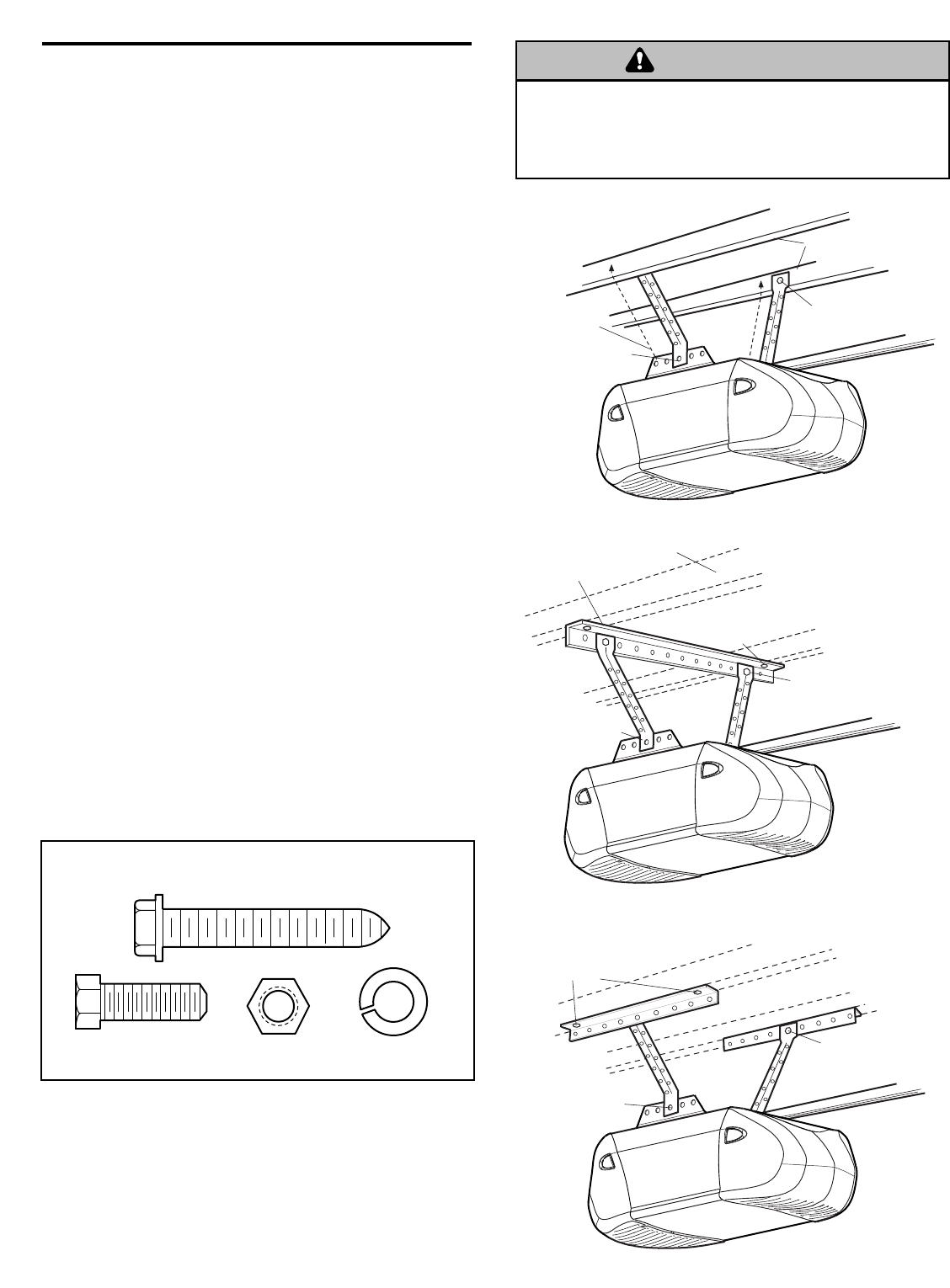
Lag Screw 5/16"-18x1-7/8"
Hex Bolt
5/16"-18x7/8"
Nut 5/16"-18
Lock Washer 5/16"
HARDWARE SHOWN ACTUAL SIZE
Figure 1
Figure 2
Figure 3
WARNING
CAUTION
WARNING
WARNING