
User Guide
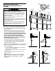


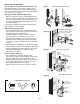


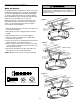
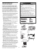
Table Of Contents
- Model PD432D 1/2 HP
- TABLE OF CONTENTS
- INTRODUCTION
- ASSEMBLY
- INSTALLATION
- STEP 1 Determine the Header Bracket Location
- STEP 2 Install the Header Bracket
- STEP 3 Attach the Rail to the Header Bracket
- STEP 4 Install The Protector System®
- STEP 5 Position the Opener
- STEP 6 Hang the Opener
- STEP 7 Install the Door Control
- STEP 8 Install the Lights
- STEP 9 Attach the Emergency Release Rope and Handle
- STEP 10 Electrical Requirements
- STEP 11 Complete the Safety Reversing Sensor Installation
- STEP 12 Fasten the Door Bracket
- STEP 13 Connect Door Arm to Trolley
- ADJUSTMENT
- OPERATION
- CARE OF YOUR OPENER
- HAVING A PROBLEM?
- PROGRAMMING
- REPAIR PARTS
- ACCESSORIES
- CHAMBERLAIN® SERVICE IS ON CALL
- HOW TO ORDER REPAIR PARTS
- WARRANTY
MOUNTING AND WIRING THE SAFETY SENSORS
• Slide a 1/4"-20x1/2" carriage bolt head into the slot on
each sensor. Use wing nuts to fasten sensors to
brackets, with lenses pointing toward each other
across the door. Be sure the lens is not obstructed by
a bracket extension. See Figure 5.
• Finger tighten the wing nuts.
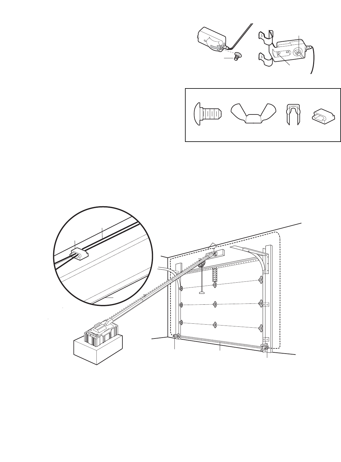
Recommended Wire Routing
1. Using insulated staples, run the wires from both
sensors to the rail at the door header (see Figure 6).
2. Run the wires through wire clip at the top of the rails.
NOTE: If your access door is near the garage door,
you may choose to install the door control at this time
and run the door control wire along the rail with the
sensor wires. If you choose this option, follow
instructions 1-3 on page 20.
Invisible Light Beam
Protection Area
Safety Reversing
Sensor
Safety Reversing
Sensor
Bell Wire
Sensor Wire
Wire Clip
Rail
Figure 6
17
Carriage Bolt
1/4"-20x1/2"
Lens
Wing Nut
1/4"-20
Figure 5
Wing Nut
1/4"-20
Staples
Carriage Bolt
1/4"-20x1/2"
Wire Clip
HARDWARE SHOWN ACTUAL SIZE