The Chamberlain Group, Inc. 845 Larch Avenue Elmhurst, Illinois 60126-1196 www.chamberlain.com GARAGE DOOR OPENER Model PD432D 1/2 HP For Residential Use Only Owner’s Manual ■ Please read this manual and the enclosed safety materials carefully! ■ Fasten the manual near the garage door after installation. ■ The door WILL NOT CLOSE unless the Protector System® is connected and properly aligned. ■ Periodic checks of the opener are required to ensure safe operation.
TABLE OF CONTENTS Introduction 2-7 Adjustment Safety symbol and signal word review . . . . . . . . . . . . . . .2 Preparing your garage door . . . . . . . . . . . . . . . . . . . . . . .3 Tools needed . . . . . . . . . . . . . . . . . . . . . . . . . . . . . . . . . .3 Planning . . . . . . . . . . . . . . . . . . . . . . . . . . . . . . . . . . . .4-5 Carton inventory . . . . . . . . . . . . . . . . . . . . . . . . . . . . . . . .6 Hardware inventory . . . . . . . . . . . . . . . . . . . . . . . . . . .
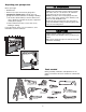
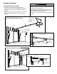
Preparing your garage door WARNING Before you begin: • Disable locks. • Remove any ropes connected to garage door. • Complete the following test to make sure your garage door is balanced and is not sticking or binding: 1. Lift the door about halfway as shown. Release the door. If balanced, it should stay in place, supported entirely by its springs. 2. Raise and lower the door to see if there is any binding or sticking.
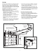
Planning Identify the type and height of your garage door. Survey your garage area to see if any of the conditions below apply to your installation. Additional materials may be required. You may find it helpful to refer back to this page and the accompanying illustrations as you proceed with the installation of your opener. Depending on your requirements, there are several installation steps which may call for materials or hardware not included in the carton.
Planning (Continued) WARNING ONE-PIECE DOOR INSTALLATIONS • Generally, a one-piece door does not require reinforcement. If your door is lightweight, refer to the information relating to sectional doors in Installation Step 12. • Depending on your door’s construction, you may need additional mounting hardware for the door bracket (Step 12). Without a properly working safety reversal system, persons (particularly small children) could be SERIOUSLY INJURED or KILLED by a closing garage door.
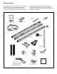
Carton Inventory Your garage door opener is packaged in one carton which contains the motor unit and all parts illustrated below. Accessories will depend on the model purchased. If anything is missing, carefully check the packing material. PARTS MAY BE STUCK IN THE FOAM. Hardware for assembly and installation is shown on the next page. Save the carton and packing material until installation and adjustment is complete.
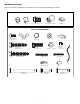
Hardware Inventory Separate all hardware and group as shown below for the assembly and installation procedures.
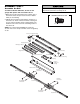
WARNING CAUTION ASSEMBLY STEP 1 Assemble the Rail To prevent INJURY from pinching, keep hands and fingers away from the joints while assembling the rail. To avoid installation difficulties, do not run the garage door opener until instructed to do so. 1. Open the rail carton and remove the contents onto a level work surface. Keep it clean and free of debris while you are working. 2. Identify the rail sections and orient the sections on a flat surface as shown. The back rail has a black gear on one end.
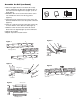
Assemble the Rail (continued) 3. Attach rail support braces to the back rail. Loosely insert 1/4-20x7/16" hex bolts into the aligned holes of the end rail and rail support brace (Figure 1). Do not finger tighten. 4. Extend the drive screw a few inches from the center rail, and slide the sleeve onto the long journal (Figure 2). HARDWARE SHOWN ACTUAL SIZE Sleeve Hex bolt 1/4-20x7/16" Clip 5. Interlock the long and short journal of the center and back rails.
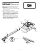
ASSEMBLY STEP 2 HARDWARE SHOWN ACTUAL SIZE Fasten the Rail to the Motor Unit and Install the Trolley NOTE: To aid in assembly and installation, replace the foam packing around the motor unit. Remove it after Installation Step 4. 1. Working on a level surface, align the rail assembly with the motor unit, as shown. 2. Slip the coupling over the rail sprocket. 3. Slide the rail through the motor unit bracket until the coupling fits securely over the motor unit sprocket. 4.
Rail Brackets ASSEMBLY STEP 3 Attach the Rail Brackets • Align rail brackets to end of rail assembly, as shown. • Insert two 1/4"-20x7/16" hex bolts. Tighten securely with a 3/8" socket. You have now finished assembling your garage door opener. Please read the following warnings before proceeding to the installation section.
INSTALLATION STEP 1 Unfinished Ceiling OPTIONAL CEILING MOUNT FOR HEADER BRACKET Determine the Header Bracket Location WARNING WARNING 2x4 Header Wall Vertical Centerline of Garage Door To prevent possible SERIOUS INJURY or DEATH: • Header bracket MUST be RIGIDLY fastened to structural support on header wall or ceiling, otherwise garage door might not reverse when required. DO NOT install header bracket over drywall. • Concrete anchors MUST be used if mounting header bracket or 2x4 into masonry.
INSTALLATION STEP 2 Install the Header Bracket Wall Mounting Holes You can attach the header bracket either to the wall above the garage door, or to the ceiling. Follow the instructions which will work best for your particular requirements. Do not install the header bracket over drywall. If installing into masonry, use concrete anchors (not provided). CEILING MOUNT ONLY The nail hole is for positioning only. You must use lag screws to mount the header bracket.
INSTALLATION STEP 3 Attach the Rail to the Header Bracket • Position the opener on the garage floor below the header bracket. Use packing material as a protective base. NOTE: If the door spring is in the way you’ll need help. Have someone hold the opener securely on a temporary support to allow the rail to clear the spring. • Position the header/rail bracket against the header bracket. • Align the bracket holes and join with a clevis pin 5/16"x2-3/4" as shown. Spacer can be installed on either side of rail.
WARNING INSTALLATION STEP 4 Install The Protector System ® Be sure power is not connected to the garage door opener BEFORE installing the safety reversing sensor. To prevent SERIOUS INJURY or DEATH from a closing garage door: • Correctly connect and align the safety reversing sensor. This required safety device MUST NOT be disabled. • Install the safety reversing sensor so beam is NO HIGHER than 6" (15 cm) above garage floor.
INSTALLING THE BRACKETS Be sure power to the opener is disconnected. Install and align the brackets so the sensors will face each other across the garage door, with the beam no higher than 6" (15 cm) above the floor. They may be installed in one of three ways, as follows. Figure 1 DOOR TRACK MOUNT (RIGHT SIDE) Door Track Lip Garage door track installation (preferred): • Slip the curved arms over the rounded edge of each door track, with the curved arms facing the door.
MOUNTING AND WIRING THE SAFETY SENSORS • Slide a 1/4"-20x1/2" carriage bolt head into the slot on each sensor. Use wing nuts to fasten sensors to brackets, with lenses pointing toward each other across the door. Be sure the lens is not obstructed by a bracket extension. See Figure 5. • Finger tighten the wing nuts. Figure 5 Wing Nut 1/4"-20 Carriage Bolt 1/4"-20x1/2" Recommended Wire Routing 1. Using insulated staples, run the wires from both sensors to the rail at the door header (see Figure 6). 2.
WARNING CAUTION INSTALLATION STEP 5 Position the Opener To prevent damage to garage door, rest garage door opener rail on 2x4 placed on top section of door. Follow instructions which apply to your door type as illustrated. SECTIONAL DOOR OR ONE-PIECE DOOR WITH TRACK A 2x4 laid flat is convenient for setting an ideal door-torail distance. • Remove foam packaging. • Raise the opener onto a stepladder. You will need help at this point if the ladder is not tall enough.
WARNING INSTALLATION STEP 6 Hang the Opener To avoid possible SERIOUS INJURY from a falling garage door opener, fasten it SECURELY to structural supports of the garage. Concrete anchors MUST be used if installing any brackets into masonry. CAUTION Three representative installations are shown. Yours may be different. Hanging brackets should be angled (Figure 1) to provide rigid support. On finished ceilings (Figure 2), attach a sturdy metal bracket to structural supports before installing the opener.
WARNING WARNING INSTALLATION CAUTIONSTEP 7 WARNING Install the Door Control Locate door control within sight of door at a minimum height of 5 feet (1.5 m) where small children cannot reach, and away from moving parts of door and door hardware. The installation surface must be smooth and flat. If installing into drywall (Figure 1), drill 5/32" holes and use anchors provided. For pre-wired installations (as in new home construction), it may be mounted to a single gang box (Figure 2).
WARNING CAUTION INSTALLATION STEP 8 Install the Lights To prevent possible OVERHEATING of the endpanel or light socket: • DO NOT use short neck or specialty light bulbs. • DO NOT use halogen bulbs. Use ONLY incandescent. To prevent damage to the opener: • DO NOT use bulbs larger than 100W. • ONLY use A19 size bulbs. • Press the release tabs on both sides of lens. Gently rotate lens back and downward until the lens hinge is in the fully open position. Do not remove the lens.
INSTALLATION WARNINGSTEP 10 WARNING Electrical Requirements To prevent possible SERIOUS INJURY or DEATH from electrocution or fire: • Be sure power is not connected to the opener, and disconnect power to circuit BEFORE removing cover to establish permanent wiring connection. • Garage door installation and wiring MUST be in compliance with all local electrical and building codes. • NEVER use an extension cord, 2-wire adapter, or change plug in any way to make it fit outlet. Be sure the opener is grounded.
WARNING CAUTION INSTALLATION STEP 12 Fasten the Door Bracket Fiberglass, aluminum or lightweight steel garage doors WILL REQUIRE reinforcement BEFORE installation of door bracket. Contact your door manufacturer for reinforcement kit. Follow instructions which apply to your door type as illustrated below or on the following page. A horizontal reinforcement brace should be long enough to be secured to two or three vertical supports. A vertical reinforcement brace should cover the height of the top panel.
ONE-PIECE DOORS Please read and comply with the warnings and reinforcement instructions on the previous page. They apply to one-piece doors also. • Center the door bracket on the top of the door, in line with the header bracket as shown. Mark either the left and right, or the top and bottom holes. • Metal Doors: Drill 3/16" pilot holes and fasten the bracket with the 1/4"-14x5/8" self-threading screws provided.
INSTALLATION STEP 13 Connect Door Arm to Trolley Inner Trolley Follow instructions which apply to your door type as illustrated below and on the following page. SECTIONAL DOORS ONLY • Make sure garage door is fully closed. Pull the emergency release handle to disconnect the outer trolley from the inner trolley. Slide the outer trolley back (away from the door) about 2" (5 cm) as shown in Figures 1, 2 and 3. • Figure 1: – Fasten straight door arm section to outer trolley with the 5/16"x1" clevis pin.
ALL ONE-PIECE DOORS 1. Assemble the door arm, Figure 4: • Fasten the straight and curved door arm sections together to the longest possible length (with a 2 or 3 hole overlap). • With the door closed, connect the straight door arm section to the door bracket with the 5/16"x1-1/4" clevis pin. • Secure with a ring fastener. 2. Adjustment procedures, Figure 5: • On one-piece doors, before connecting the door arm to the trolley, the travel limits must be adjusted.
WARNING ADJUSTMENT STEP 1 Adjust the UP and DOWN Travel Limits Without a properly installed safety reversal system, persons (particularly small children) could be SERIOUSLY INJURED or KILLED by a closing garage door. • Incorrect adjustment of garage door travel limits will interfere with proper operation of safety reversal system. • If one control (force or travel limits) is adjusted, the other control may also need adjustment. • After ANY adjustments are made, the safety reversal system MUST be tested.
WARNING ADJUSTMENT STEP 2 Adjust the Force Without a properly installed safety reversal system, persons (particularly small children) could be SERIOUSLY INJURED or KILLED by a closing garage door. • Too much force on garage door will interfere with proper operation of safety reversal system. • NEVER increase force beyond minimum amount required to close garage door. • NEVER use force adjustments to compensate for a binding or sticking garage door.
WARNING ADJUSTMENT STEP 3 Test the Safety Reversal System Without a properly installed safety reversal system, persons (particularly small children) could be SERIOUSLY INJURED or KILLED by a closing garage door. • Safety reversal system MUST be tested every month. • If one control (force or travel limits) is adjusted, the other control may also need adjustment. • After ANY adjustments are made, the safety reversal system MUST be tested. Door MUST reverse on contact with 1-1/2" high (3.
WARNING OPERATION IMPORTANT SAFETY INSTRUCTIONS WARNING To reduce the risk of SEVERE INJURY or DEATH: 1. READ AND FOLLOW ALL WARNINGS AND INSTRUCTIONS. 2. ALWAYS keep remote controls out of reach of children. NEVER permit children to operate or play with garage door control push buttons or remote controls. 3. ONLY activate garage door when it can be seen clearly, it is properly adjusted, and there are no obstructions to door travel. 4. ALWAYS keep garage door in sight until completely closed.
Using the Wall-Mounted Door Control THE MULTI-FUNCTION DOOR CONTROL Press the lighted push button to open or close the door. Press again to reverse the door during the closing cycle or to stop the door while it's opening. To Open the Door Manually WARNING Lighted Push Button To prevent possible SERIOUS INJURY or DEATH from a falling garage door: • If possible, use emergency release handle to disengage trolley ONLY when garage door is CLOSED.
THE REMOTE CONTROL BATTERY CARE OF YOUR OPENER LIMIT AND FORCE ADJUSTMENTS: Weather conditions may cause some minor changes in door operation 9 1 requiring some re-adjustments, 7 3 kg kg 5 particularly during the first year of operation. FORCE CONTROLS Pages 27 and 28 refer to the limit and force adjustments. Only a screwdriver is required. Follow the instructions carefully. Repeat the safety reverse test LIMIT CONTROLS (Adjustment Step 3, page 29) after any adjustment of limits or force.
HAVING A PROBLEM? Bell Wire 1. My door will not close and the light bulbs blink on my motor unit: The safety reversing sensor must be connected and aligned correctly before the garage door opener will move in the down direction. • Verify the safety sensors are properly installed, aligned and free of any obstructions. Refer to Installation Step 4: Install The Protector System®. • Check diagnostic LED for flashes on the motor unit then refer to the Diagnostic Chart on the following page.
Diagnostics Located On Motor Unit KG KG Installed Safety Reversing Sensor LED or Diagnostic LED "Learn" Button Diagnostic Chart 1 FLASH Safety reversing sensors wire open (broken or disconnected). OR 2 FLASHES Safety reversing sensors wire shorted or black/white wire reversed. 3 FLASHES Door control or wire shorted. 4 FLASHES Safety reversing sensors slightly misaligned (dim or flashing LED). 5 FLASHES Motor overheated or possible RPM sensor failure. Unplug to reset.
PROGRAMMING NOTICE: If this Security✚® garage door opener is operated with a non-rolling code transmitter, the technical measure in the receiver of the garage door opener, which provides security against code-theft devices, will be circumvented. The owner of the copyright in the garage door opener does not authorize the purchaser or supplier of the non-rolling code transmitter to circumvent that technical measure.
To Add, Reprogram or Change a Keyless Entry PIN NOTE: Your new Keyless Entry must be programmed to operate your garage door opener. USING THE “LEARN” BUTTON USING THE MULTI-FUNCTION DOOR CONTROL LO C K L IG H T 1. Press and release the “learn” button on motor unit. The learn indicator light will glow steadily for 30 seconds. 2. Within 30 seconds, enter a four digit personal identification number (PIN) of your choice on the keypad. Then press and hold the ENTER button. 3.
REPAIR PARTS Rail Assembly Parts 1 8 2 7 6 KEY PART NO. NO. 5 4 3 Installation Parts 4 81C275 41A6263 3 4 5 12B890 12B900 41A6264 6 7 8 12B889 41C4677 41A4836 28A143 2 1 3 KEY NO. LOCK LIGHT G LIN CEI 6 T UN MO LY ON UP 7 5 NOT 1 2 ICE 10 11 9 8 13 1 2 3 4 5 6 7 8 9 10 11 12 13 12 37 PART NO.
Motor Unit Assembly Parts 13 9a 9 1 10 2 14 6a 3 12 4 5 8 7 6 Brown Wire (Down) Contact LIMIT SWITCH ASSY. DN UP Drive Gear Center Limit Contact 11 14 (Up) Contact KEY NO. PART NO. DESCRIPTION KEY NO. PART NO. DESCRIPTION 1 2 3 4 5 6 6a 7 31C568 41B4245 30B620 41A3150 41D4671 41A6241 20B21-1 41C4672 Drive shaft cover Line cord Capacitor – 1/2 Terminal block w/screws Limit switch assembly Motor drive assy.
ACCESSORIES 953D 3-Button Security✚® Remote Control: 956D 3-Button Mini-Remote Control with Security✚®: With key ring and fastening strip. 7702CB Outside Quick Release: Required for a garage with NO access door. CLLAD Remote Light Control: Enables homeowner to turn on a lamp, television or other appliance from their car with their garage door opener remote or from anywhere in their home with an additional Chamberlain Security✚® remote.
HOW TO ORDER REPAIR PARTS CHAMBERLAIN® SERVICE IS ON CALL OUR LARGE SERVICE ORGANIZATION SPANS AMERICA INSTALLATION AND SERVICE INFORMATION IS AS NEAR AS YOUR TELEPHONE. SIMPLY DIAL OUR TOLL FREE NUMBER: Selling prices will be furnished on request or parts will be shipped at prevailing prices and you will be billed accordingly. WHEN ORDERING REPAIR PARTS, ALWAYS GIVE THE FOLLOWING INFORMATION: • PART NUMBER • PART NAME • MODEL NUMBER 1-800-528-9131 ADDRESS ORDERS TO: www.chamberlain-diy.