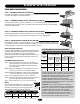
CO NT RO LL ER GL MODEL HS670 HEAVY DUTY HYDRAULIC SLIDE GATE OPERATOR 2 YEAR WARRANTY Serial # ________________________ (located on electrical box cover) Installation Date __________________ MODEL HS670 IS FOR VEHICULAR PASSAGE GATES ONLY AND ARE NOT INTENDED FOR PEDESTRIAN PASSAGE GATE USE BO AR D
TABLE OF CONTENTS OPERATOR SPECIFICATIONS IMPORTANT NOTE Carton Inventory . . . . . . . . . . . . . . . . . . . . . . . . . . . . . . . . . . . . .2 Operator Features . . . . . . . . . . . . . . . . . . . . . . . . . . . . . . . . . . . .3 Operator Dimensions and Horsepower Chart . . . . . . . . . . . . . . .4 UL325 Model Classifications . . . . . . . . . . . . . . . . . . . . . . . . . . . .
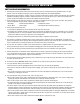
O P E R AT O R S P E C I F I C AT I O N S OPERATOR FEATURES A. MOTOR 1 AND 2 HP The motors used in the HS670 GC and HS670 GI are T.E.F.C. (totally enclosed, fan cooled) and operate at 3450 R.P.M. They incorporate a built-in manually resettable thermal overload. B. DIRECTIONAL VALVE Directional valve is 3 position, 4 way. It incorporates 2 solenoids which are 24 VDC. The power required for operation is rectified from 24 VAC. C. HYDRAULIC BRAKE Dual valve system limits gate over travel. D.
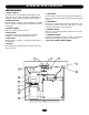
O P E R AT O R S P E C I F I C AT I O N S OPERATOR DIMENSIONS AND HORSEPOWER CHART MODEL HS670 GC • 1 HP Motor Gate Speed – 12"/sec. Maximum Gate Weight – 3000 lbs. Maximum V-Track Gate Width – 80 ft. MODEL HS670 GI • 1 HP Motor Gate Speed – 18"/sec. Maximum Gate Weight – 3000 lbs. Maximum V-Track Gate Width – 80 ft. MODEL HS670 GI • 2 HP Motor Gate Speed – 18"/sec. Maximum Gate Weight – 5000 lbs. Maximum V-Track Gate Width – 80 ft.
O P E R AT O R S P E C I F I C AT I O N S UL325 MODEL CLASSIFICATIONS CLASS I – RESIDENTIAL VEHICULAR GATE OPERATOR A vehicular gate operator (or system) intended for use in a home of one-to four single family dwellings, or a garage or parking area associated therewith.
O P E R AT O R WA R N I N G S SAFETY INSTALLATION INFORMATION 1. Vehicular gate systems provide convenience and security. Gate systems are comprised of many component parts. The gate operator is only one component. Each gate system is specifically designed for an individual application. 2. Gate operating system designers, installers and users must take into account the possible hazards associated with each individual application.
O P E R AT O R WA R N I N G S SUGGESTED ENTRAPMENT PROTECTION DEVICE LOCATIONS GATE SYSTEM (COMMERCIAL SLIDE GATE) Sentex Telephone Entry System / Access Control Open Edge Photo Eye For Open Cycle Close Edge Run Twisted Wire From Loop To Detector STREET 4' Typical 8' Seal Loops Interrupt Loop 1-1/2" 4' Typical 4' Typical Photo Eye For Close Cycle Loop Wire Layer Interrupt Loop COMPLEX OR PARKING LOT 4' Typical 1/4" Or As Required For Loop Wire Width GATE SYSTEM (MASTER/SECOND SLIDE GATE) Open
O P E R AT O R WA R N I N G S SAFETY PRECAUTIONS FOR OPEN ROLLER GATES AND ORNAMENT “GRILL TYPE” GATES Gate Edge on Rear of Gate for Open Direction Gate Edge on Fence Post for Open Direction WARNING Gate Edge on Leading Edge of Gate for Close Direction WARNING Photo Beam for Open Direction • Injuries occur when people get their hands or feet caught between the top or bottom of the gate and the gate roller. These potential pinch-points should be guarded against at all times.
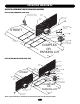
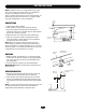
I N S TA L L AT I O N NOTES: Installation shown is for a right-handed unit (on right side of gate opening when inside looking out). Left-handed is opposite. For left-handed conversion, see page 17. If there is suitable existing concrete at area of unit mounting, use dimensioning procedure described in step 1. Conduit locations may require modifications to suit your application. “Gate” Shown Open CONCRETE PAD 1. Layout concrete pad as detailed. 2. Locate conduit, as required, prior to pouring concrete.
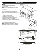
I N S TA L L AT I O N VENT CAP IMPORTANT: Do Not Use Cover Handles to Move Unit 1. Remove the threaded plug from the pump tank. 2. Install the vent cap. NOTE: Never run the operator without the vent cap installed. LIMIT SHOES Loosen Screw to Remove Cover NOTE: The limit shoes are slotted, so minor adjustments may be made later for the fine tuning of the fully open and close positions. Also, note that the limit switches themselves may be slightly adjusted up or down. 1.
I N S TA L L AT I O N GATE STOPS Gate Stops 1. When properly installed the gate will open or close in approximately 3" to 4" after limit shoe shuts the unit off, the “gate stop” will contact the upper drive wheel stopping the gate. 2. After operator has been installed the limit shoes have been attached to the top of the drive rail, locate and install the (2) “gate stops” to the top of the drive rail. NOTE: The 7" dimension is a reference.
NING WWARNING IRING ION WARNING To reduce the risk of SEVERE INJURY or DEATH: • ANY maintenance to the operator or in the area near the operator MUST not be performed until disconnecting the electrical power and locking-out the power via the operator power switch. Upon completion of maintenance the area MUST be cleared and secured, at that time the unit may be returned to service. • Disconnecting power at the fuse box BEFORE proceeding.
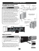
WIRING ON/OFF SWITCH POWER WIRING On/Off Switch NOTES: Before running power wiring refer to wiring specifications on previous page for correct wire gauges. Secure all electrical power connections inside the disconnect switch electrical box. Refer to electrical wiring diagram on pages 30 and 31.
ADJUSTMENT HALL EFFECT SENSOR ADJUSTMENT WARNING NOTE: Normally the hall effect sensor does not need adjustment, but may go out of alignment due to shipping vibration or rough handling. These operators use an internal entrapment protector system. This system consists of the control board, magnet, and hall effect sensor. It may become necessary to adjust the sensor for correct alignment. To do so please perform the following steps: 1. The hall effect sensor must be centered over the magnet.
PROGRAMMING UL325 ENTRAPMENT PROTECTION Force Control GL Controller Board PRIMARY ENTRAPMENT PROTECTION ADJUSTMENTS Force Control Set the force control pot such that the unit will complete a full cycle of gate travel but can be reversed off an obstruction without applying an unreasonable amount of force. On most operators this will be around the middle of the range.
PROGRAMMING CONTROL BOARD ILLUSTRATION Connector Master/Second (J4) Connector Main Terminal Wiring (J1) Dip Switch Master/Second (S4) Timer to Close Force Adjustment Dip Switch (S2) Dip Switch (S1) Diagnostic LED Connector (J2) Limit LEDs Connector SAMS (J5) Motor Learn Button (S3) Relay Drive Troubleshooting LEDs (D6) Terminal Troubleshooting LEDs (D11) 16
PROGRAMMING PROGRAM SETTINGS (DIP SWITCH S1) NOTE: For all S1, S2 and S4 switch settings to take effect, the Save Mode switch must be set to the off position. TIMER TO CLOSE TIMER TO CLOSE ENABLE This switch (S1-1) enables the auto close timer. The timer to close feature works in conjunction with the potentiometer located on the board.
PROGRAMMING PROGRAM SETTINGS (DIP SWITCH #2) CONT’D EDGE/PHOTO OPEN This switch (S2-3) selects edge or photo sensor for the gate opening protection input. Open Photo Eye (Pause): When the controller is configured for photo eyes, the input functions to pause the gate during the opening cycle. Once the input is cleared the gate continues to open.
PROGRAMMING PROGRAMMING THE RADIO RECEIVER WARNING SET SECURITY MODE To prevent possible SERIOUS INJURY or DEATH from electrocution: • Be sure power is not connected BEFORE installing the receiver. To prevent possible SERIOUS INJURY or DEATH from a moving gate or garage door: • ALWAYS keep remote controls out of reach of children. NEVER permit children to operate, or play with remote control transmitters.
OPTIONAL CONTROL DEVICES SEQUENCED ACCESS MANAGEMENT SYSTEM (SAMS) SAMS DEFINITION The Sequenced Access Management System or SAMS allows the customer more control when managing vehicular entrances to areas such as industrial complexes, businesses and airports.
OPTIONAL CONTROL DEVICES ACCESSORY WIRING 1 STOP/RESET AUXILIARY CONTROL WIRING Terminals 6 & 5 (Com) - Open These terminals are intended for use as a general open control. Accessories that may be wired to this input include: Telephone Entry Systems, Radio Receiver (Commercial Applications), Exit Loop Detector, Keypads, 7-Day Timer. NOTE: Will not override a double entrapment (signalled by the gate stopped and entrapment alarm on).
OPTIONAL CONTROL DEVICES CONTROL CONNECTION DIAGRAMS J1 TERMINAL BLOCK 1 2 4 3 5 6 7 8 9 10 11 12 13 14 Soft Open Input (N.O.) 1 2 3 4 5 6 7 8 9 10 11 12 13 14 15 16 17 18 19 20 21 22 23 24 25 26 27 28 1 2 3 5 6 7 8 9 Hard Close Control Input (N.O.) 0 # R1 R2 R3 R4 OPEN CLOS E Hard Open Control Input (N.O.) ST OP 24 VAC OPEN 24VAC ACCESSORY POWER Can be found at terminals R1 and R2 located on radio terminal block. CLOS E Stop/Reset Control Input (N.C.
O P E R AT I O N A N D M A I N T E N A N C E NING WARNING IMPORTANT SAFETY INSTRUCTIONS ION WARNING To reduce the risk of SEVERE INJURY or DEATH: 1. READ AND FOLLOW ALL INSTRUCTIONS. 2. NEVER let children operate or play with gate controls. Keep the remote control away from children. 3. ALWAYS keep people and objects away from the gate. NO ONE SHOULD CROSS THE PATH OF THE MOVING GATE. 4. Test the gate operator monthly.
TROUBLESHOOTING GL BOARD FEATURES Force Control DIAGNOSTICS (LEDS AND CODES) There are three diagnostic LEDs. Two red LEDs (OL, CL) are indicators for the open and close limits. The LEDs are illuminated when the limit switch contacts are closed. The third amber LED (DIA) is used to blink out diagnostic codes. The number is the count of the number of times the LED is on in an 8 second period. The LED is on for approximately 1/2 second and repeats every second until the number is reached.
TROUBLESHOOTING FAULT OPERATOR FAILS TO RUN POSSIBLE CAUSE 1) No stop control 2) Fault in the operator check the yellow diagnostic LED at the top right of the GL board next to the programming dip switches. 3) An accessory is active or malfunctioning check the red input status LEDs, D11-D31 4) Low or no high voltage power.
TROUBLESHOOTING FAULT MASTER OR SECOND OPERATOR IS NOT FUNCTIONING PROPERLY POSSIBLE CAUSE 1) Failure to cycle power after setup 3) Master or second unit is not programmed correctly 1) Entrapment (force pot) incorrectly set ➤ This pot must be set so that the gate will run smoothly normally and 2) Gate is binding or not running smoothly ➤ Disengage the manual release and roll gate open and close by hand at reverse when encountering an obstruction.
TROUBLESHOOTING HYDRAULIC SYSTEM TROUBLESHOOTING SYMPTOM (A) BYPASS VALVE: It MUST be in the “automatic” position (horizontal). If it is in the manual position, no fluid gets to the drive motors, so they won’t turn. If the bypass lever is between positions, fluid will be bled off, so motors will turn slower. (B) PUMP: Air may be in the system, allow about 15 seconds for air to dissipate. Filter may be clogged. Check fluid level. (C) DIRECTION VALVE: Press and hold the manual override button on valve.
TROUBLESHOOTING HYDRAULIC SYSTEM INFORMATION HYDRAULIC MOTORS 1. The two hydraulic motors are “ROLLER VANE” type and are machined to be free wheeling. Each motor has a displacement of 12 in3/rev. 2. The speed of each is approximately 55 RPM which equates to a gate speed of approximately 18"/ sec. for classes 3 and 4. For classes 1 and 2, the motor’s speed is 37 RPM and gate speed of 12"/sec. 3. The drive wheels are: HS670 1HP (1-1/2" w. x 6" dia.) HS670 2HP (2" w. x 6" dia.). Circumference of both: 18.
TROUBLESHOOTING HYDRAULIC DON’TS 1. DO NOT use only one wrench to lighten hose swivel fittings. Use two wrenches, one to tighten and one to hold back opposite fitting. See illustration above. 2. DO NOT pour detergent oil, mineral spirits, diesel fuel, fuel oil or gasoline into the tank. NEVER USE BRAKE FLUID. Only use hydraulic oil. 3. DO NOT put pipe dope or teflon tape on any part of hose fittings. 4. DO NOT remove vent cap except to fill tank with fluid. 5.
SINGLE PHASE WIRING DIAGRAM 01-G10028-1 EMMERSON MOTOR CONNECTIONS BALDOR MOTOR CONNECTIONS OVERLOAD (SEE NOTE 6) (LEFT) (RIGHT) NOTES: 1. Transformer primary voltage same as operator line voltage 24V secondary 60VA. 2. Wire color: 120V black, 230V orange. 3. Coil voltage same as line voltage. 4. (B+) and (B-) are 100db safety alarms. 5. For single button radio function, perform optional wire change.
THREE PHASE WIRING DIAGRAM 01-G10028-3 4 (LEFT) (RIGHT) NOTES: 1. Transformer primary voltage same as operator line voltage 24V secondary 60VA. 2. Wire color: 230V orange, 460V violet. 3. Coil voltage same as line voltage. 4. (B+) and (B-) are 100db safety alarms. 5. For single button radio function, perform the optional wire change.
ELECTRICAL BOX COMPLETE ELECTRICAL BOX REPLACEMENT KITS To order a complete electrical box replacement kit, add a Kprefix to the model number of your operator.
I L L U S T R AT E D PA R T S 9 13 3 7 16 5 4 6 3 10 2 14 17 12 3 10 15 11 1 8 INDIVIDUAL PARTS AND KITS ITEM 1 2 3 4 5 6 7 8 9 10 11 12 13 14 15 16 17 PART # K20-1100 K20-3100C-4 K20-3200C-4 K32-19007 K32-19008 K75-19103 K75-19102 K75-19101 K75-19100 K75-19099 K75-19098 K75-19097 K75-19096 K75-19095 K75-19094 29-19202 MG49130 K75-19090 K74-G0589 29-19203 80-19011 K75-19104 DESCRIPTION Motor, 1HP 115/230V 1PH Motor, 1HP 230/460V 3PH Motor, 2HP 230/460V 3PH Hydraulic Pump, Class 3&4 Hydrauli
WARRANTY POLICY LIFTMASTER ® TWO YEAR LIMITED WARRANTY The Chamberlain Group, Inc. warrants to the final purchaser of this product, for the structure in which this product is originally installed, that it is free from defect in materials and/or workmanship for a period of two years from the date of purchase. The proper operation of this product is dependent on your compliance with the instructions regarding installation, operation, maintenance and testing.
O P E R AT O R N O T E S 35
REPAIR PARTS AND SERVICE HOW TO ORDER REPAIR PARTS OUR LARGE SERVICE ORGANIZATION SPANS AMERICA For installation and service information, call our TOLL FREE number: 1-800-528-2806 www.liftmaster.com When ordering repair parts please supply the following information: PART NUMBER DESCRIPTION MODEL NUMBER ADDRESS ORDER TO: THE CHAMBERLAIN GROUP, INC. Technical Support Group 6020 Country Club Road Tucson, AZ 85706 01-18826F ©2006, The Chamberlain Group, Inc.