
Inc. Quad M-module Carrier User Manual


i4000 - Quad M-module carrier for VMEbus
User Manual Version: 1.2
AcQuisition Technology bv
P.O. Box 627, 5340 AP
Oss, The Netherlands Page 7 of 25
2. PRODUCT OVERVIEW
2.1. INTRODUCTION
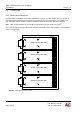
The i4000 provides a compact high-performance VMEbus gateway to the M-module interface. The i4000 has
a 6U form factor. Four M-modules can be mounted on the i4000.
The M-module interface of the i4000 complies with the M-module Specification. The M-module specification is
ANSI approved. The M-module interface features A8, A24, D16 and D32 access types.
2.2. TECHNICAL OVERVIEW
Below an overview of the i4000 is listed.
VME interface
• A24/A16, D16/D08(EO)
• D08(O) (DYN) interrupt vector (vector unique per module)
• I(x) interrupt level (on the i4000/NP2 this is programmable per module)
M-module interface
• 4 M-module Interfaces (A08/A24, D16/D32)
• INTA software-end-of interrupt
• INTB hardware-end-of-interrupt
• INTC interrupt-vector-transfer
Connections
• Via 25 pole sub-D connector on the front of the M-module
• Via 24 pole I/O connector on the i4000 for rear I/O (only on the i4000/P2 version)
• Via P1 to VMEbus
• Via VME-P2 connector (only on the i4000/P2 version)
Note: The P2 on an i4000/P2 can be used to create an alternative I/O-path for M-modules placed on the
carrier board. The M-modules must support an alternative I/O-path (usually recognizable by a 24-pole
female header near the DSUB-25).
IMPORTANT: The i4000/P2 cannot be used in a VMEbus rack with monolithic backplane or a P2/J2
backplane. For these cases use an i4000/NP2 instead.