U S E R ' S VXI PULSE GENERATOR MODULE MODEL VX462B Manual Part No: 11026339D M A N U A L
COPYRIGHT C&H Technologies, Inc. (C&H) provides this manual "as is" without warranty of any kind, either expressed or implied, including but not limited to the implied warranties of merchantability and fitness for a particular purpose. C&H may make improvements and/or changes in the product(s) and/or program(s) described in this manual at any time and without notice. This publication could contain technical inaccuracies or typographical errors.
AMENDMENT NOTICE C&H Technologies, Inc. makes every attempt to provide up-to-date manuals with the associated equipment. Occasionally, changes are made to the equipment wherein it is necessary to provide amendments to the manual. If any amendments are provided for this manual they are printed on colored paper and will be found at the rear of this manual. NOTE The contents of any amendment may affect operation, maintenance, or calibration of the equipment.
INTRODUCTION This manual describes the functional operation of the C&H Model VX462B VXI Pulse Generator (Part No. 11026335). This module is one of a number of test and data acquisition/control modules in the VME and VXI format provided by C&H. Contained within this manual is information on the physical and electrical specifications, installation and startup procedures, operating procedures, functional analysis, and figures and diagrams required to adequately support this product.
TABLE OF CONTENTS 1.0 GENERAL DESCRIPTION ............................................................................................. 1 1.1 PURPOSE OF EQUIPMENT ............................................................................... 1 1.2 SPECIFICATIONS OF EQUIPMENT.................................................................. 1 1.2.1 Key Specifications................................................................................ 1 1.2.2 Electrical............................................
LIST OF FIGURES Figure 1. Electrical Timing and Output Characteristics ........................................................... 2 Figure 2. Simplified Block Diagram........................................................................................ 7 Figure 3. Hardware Configurable Controls ............................................................................. 7 Figure 4. Front Panel..............................................................................................................
1.0 GENERAL DESCRIPTION The VX462B is a B-size VXIbus compatible programmable 20 MHz pulse generator with an additional 40 MHz square wave function. The module can output single or double pulse patterns that can be continuous streams or externally triggered or gated. The pulse repetition interval and pulse width are programmable and a delay time may be programmed in the delayed or double pulse modes. The output amplitude is also programmable. 1.
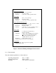
Pulse Repetition Interval Range: 50ns to 1 sec, in 6 ranges Resolution: 25ns min., 10 bits Accuracy: (1%+15ns) of the programmed value Pulse Width Range: Resolution: Accuracy: 25ns to 1sec, in 6 ranges 25ns min., 10 bits (1%+15ns) of the programmed value Delay Timing (from Trigger Out) Range: 25ns to 1 sec, range slaved to Pulse Repetition Interval range Resolution: 25ns min., 10 bits Accuracy: (1%+15ns) of the programmed value + 25ns to 75ns synchronization time Pulse Output Impedance: 2-5 ohms (max.
1.2.5 Bus Compliance The module complies with the VXIbus Specification Revision 1.4 for B-size register based modules and with VMEbus Specification ANSI/IEEE STD 1014-1987 and IEC 821.
4
2.0 INSTALLATION 2.1 UNPACKING AND INSPECTION In most cases the VX462B is individually sealed and packaged for shipment. Verify that there has been no damage to the shipping container. If damage exists then the container should be retained as it will provide evidence of carrier caused problems. Such problems should be reported to the carrier immediately as well as to C&H.
6
3.0 FUNCTIONAL DESCRIPTION 3.1 GENERAL The VX462B is configured, controlled, and statused through on-board registers accessible through the VXI backplane. These registers control the mode of operation, pulse repetition interval, pulse width, delay time, output amplitude and an output relay. A simplified block diagram of the module is shown in Figure 2.
3.3 INDICATORS Two LED indicators are provided on the front panel. One indicates the MODID status and the other indicates the board status. VX462B MODID: This front panel LED illuminates whenever the host processor applies the MODID signal to the slot the module is occupying. MODID RUN: 3.4 This front panel LED illuminates when the modules is actively outputting pulses. RUN TRIG IN CONNECTORS 3.4.
3.5 CONFIGURATION REGISTERS There are several types of registers used to configure and control the VX462B. The VXI configuration registers provide for control and status as required by the VXIbus specification. The other register provides board-level control and status of the pulse repetition interval, pulse width, trigger modes and delay times, and output amplitude. An address map of the registers is shown in Table I. 3.5.
00 Bit Write Read VXI ID 15 14 Device Class 13 12 11 10 9 8 7 Not Used Address Space 6 5 4 3 2 1 0 0 Not Used Manufacturer ID Device Class Device Class (Register Based = binary 11) Address Space Address Space (A16 Only = binary 11) Manuf.
3.5.2 Pulse Configuration Registers Pulse Repetition Interval Register (08) This read/write register controls the pulse repetition interval and the state of the output relay. See Figure 6 for details.
Delay Register (0A) This read/write register controls delay of the primary pulse from the trigger out or the delay of the second pulse of a double pulse from the trigger out. See Figure 7 for details. 0A Bit Write Delay Register 15 14 13 12 11 10 9 8 7 6 Not Used Not Used Read 5 4 3 2 1 0 Delay Multiplier Delay Multiplier Delay Multiplier Delay Multiplier (period = Delay Multiplier PRI Range) NOTES: 1) The Range field is programmable in the PRI register.
Pulse Control Register (0E) This read/write register configures the operating mode of the pulse. See Figure 9 for details.
Low/High Level Reference Register (10 & 12) Two 12 bit Digital to Analog Converters (DAC) are used to create the low and high level references to the output logic. These registers are write only. See Figure 10 for details. 10 Low Level Reference Registers Bit Write 15 Read 1 14 13 12 11 10 9 8 7 Not Used 1 6 5 4 3 2 1 0 1 1 1 1 Reference Voltage 1 1 Ref. Voltage 2 Ohm Output Imp: 50 Ohm Output Imp: 1 1 1 1 1 1 1 1 000h = -10.0 V, 800h = 0.0 V, FFFh = 10.
4.0 OPERATING INSTRUCTIONS The VX462B provides three normal modes, three triggered modes, and three special modes of operation, along with voltage level programming, output disconnect, and pulse enable controls. A functional block diagram is show in Figure 11. These operational modes are configured, controlled, and statused through on-board registers accessible through the VXI backplane. Refer to paragraph 3.5.2 for register bit definitions.
4.2 PROGRAMMING SEQUENCE The RUN bit in the Pulse Control Register is the basic On/Off control for pulse generation. A separate output relay connects/disconnects the generated pulse to/from the BNC connector. The output relay is controlled by the OEN bit in the PRI Register. Before enabling the RUN control bit or output relay, be sure to program all of the timing and voltage level registers as prescribed in this manual.
4.4 TRIGGERED MODES OF OPERATION The pulse stream can be programmed to run continuously, output a single function when triggered, or output continuously as long as the gate (trigger in) is high (i.e., free run, trigger, or gated repetition.). All three trigger modes are described below. The RUN control bit must be set for any mode of operation to produce a pulse stream. 4.4.1 Free When the FRE and RUN bits are programmed high, a continuous stream of pulses are generated at the output driver.
4.6 OUTPUT VOLTAGE LEVEL PROGRAMMING Two 12 bit digital to analog converters (DAC's) provide the output switch reference voltages. The DAC's have built in safety features to prevent damage if the positive reference is programmed below the negative voltage; however, the user should try to prevent this situation. The output logic switches the high and low reference voltages into a power op-amp output stage.
5.0 TROUBLE ANALYSIS 5.1 BUILT IN TEST AND DIAGNOSTICS Built in test functions are provided for the VX462B in the form of read back registers. The VXIbus registers perform as defined in the VXIbus specification and the timing and control registers have read back capability for data verification and test. 5.2 TROUBLE ANALYSIS GUIDE The first approach to troubleshooting is to attempt a A16 VXIbus access. A successful access (read or write) will not produce a bus error.
20
APPENDIX A - BOARD LAYOUT A-1
A-2
APPENDIX B - CONNECTORS PIN 1 2 3 4 5 6 7 8 9 10 11 12 13 14 15 16 17 18 19 20 21 22 23 24 25 26 27 28 29 30 31 32 C D08 D09 D10 D11 D12 D13 D14 D15 GND SYSRESET* LWORD* AM5 A23 A22 A21 A20 A19 A18 A17 A16 A15 A14 A13 A12 A11 A10 A09 A08 +12 V +5 V B BG0IN* BG0OUT* BG1IN* BG10UT* BG2IN* BG20UT* BG3IN* BG3OUT* AM0 AM1 AM2 AM3 GND GND IRQ7* IRQ6* IRQ5* IRQ4* IRQ3* IRQ2* IRQ1* +5 V A D00 D01 D02 D03 D04 D05 D06 D07 GND DS1* DS0* WRITE* DTACK* _ _ _ IACK* IACKIN* IACKOUT* AM4 A07 A06 A05 A04 A03 A02 A01 -12
PIN 1 2 3 4 5 6 7 8 9 10 11 12 13 14 15 16 17 18 19 20 21 22 23 24 25 26 27 28 29 30 31 32 C GND GND GND GND GND GND - B +5V GND GND +5V GND GND +5V A GND GND GND GND MODID GND - Figure B-2.
BNC TRIGGER/GATE INPUT TRIG IN TRIGGER OUTPUT TRIG OUT PULSE PULSE OUT FRONT VIEW Figure B-3.
B-4
NOTES
READER'S COMMENT FORM Your comments assist us in improving the usefulness of C&H's publications; they are an important part of the inputs used for revision. C&H Technologies, Inc. may use and distribute any of the information that you supply in any way that it believes to be appropriate without incurring any obligation whatsoever. You may, of course, continue to use the information which you supply.
INSTRUCTIONS In its continuing effort to improve documentation, C&H Technologies, Inc. provides this form for use in submitting any comments or suggestions that the user may have. This form may be detached, folded along the lines indicated, taped along the loose edge (DO NOT STAPLE), and mailed. Please try to be as specific as possible and reference applicable sections of the manual or drawings if appropriate.