U S E R ' S ETHERNET M-MODULE CARRIER MODEL EM405D Manual Part No: 11028854 M A N U A L
COPYRIGHT C&H Technologies, Inc. (C&H) provides this manual "as is" without warranty of any kind, either expressed or implied, including but not limited to the implied warranties of merchantability and fitness for a particular purpose. C&H may make improvements and/or changes in the product(s) and/or program(s) described in this manual at any time and without notice. This publication could contain technical inaccuracies or typographical errors.
DOCUMENT REVISION NOTICE C&H Technologies, Inc. makes every attempt to provide up-to-date manuals with the associated equipment. Occasionally, throughout the life of an instrument, changes are deemed necessary to equipment related documentation. The latest revision of our documentation is available for download from our web site at http://www.chtech.com. NOTE The contents of any amendment may affect operation, maintenance, or calibration of the equipment.
INTRODUCTION This manual describes the operation and use of the C&H Model EM405D Ethernet M-Module Carrier (Part Number 11028850). This instrument is one of a number of M-module carriers provided by C&H. Contained within this manual are the physical and electrical specifications, installation and startup procedures, functional description, and configuration and programming guidelines to adequately use the product.
TABLE OF CONTENTS 1.0 GENERAL DESCRIPTION ............................................................................................ 1 1.1 PURPOSE OF EQUIPMENT............................................................................................. 1 1.2 FEATURES AND SPECIFICATIONS .............................................................................. 1 1.2.1 Key Features ................................................................................................................ 1 1.2.
4.3.5 EM405D Configuration/Status Registers ...................................................................23 4.4 CONTROLLING THE TRIGGERS..................................................................................26 4.5 FAN AND TEMPERATURE CONTROL........................................................................27 APPENDIX A - CONNECTORS ............................................................................................ A-1 APPENDIX B – WIRED ETHERNET DEFAULT SETTINGS..............
1.0 GENERAL DESCRIPTION The EM405D Ethernet M-Module carrier provides complete Ethernet connectivity to up to two industry standard single-wide or one double-wide M or MA modules. The carrier provides full access to the M/MA module I/O space via the standard TCP/IP networking protocol. M-module triggers are also fully supported allowing them to be connected externally to a 9-pin DSUB connector or to an adjacent M-module.
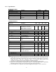
1.2.2 Specifications MAXIMUM RATINGS Parameter Condition Operating Temperature Non-Operating Temperature Humidity Input DC Power Level Power Consumption External Trigger Input non-condensing Rating Units 0 to +60 C -40 to +75 C % V max. Watts V V 5 to 95 12.
1.3 Electrical The EM405D only requires a +12V DC power input. The +12V input is internally converted to the +3.3V power required by the carrier and the +5V, +12V, and -12V power required by the Mmodules. A maximum of 30 watts is required to support the carrier and two M-modules operating at the maximum allowed power consumption. The maximum allowed power consumption for each M-module is 1A of +5V and 200ma each of +12V and -12V. The EM405D uses power-off resetable fuses on the incoming +12V supply.
1.7 APPLICABLE DOCUMENTS ANSI/VITA 12-1996 American National Standard for The Mezzanine Concept MModule Specification, Approved May 20, 1997, VMEbus International Trade Association, 7825 E. Gelding Dr. Suite 104, Scottsdale, AZ 85260-3415, E-mail: info@vita.com, www.vita.com IEEE-802.3 (ANSI 8802.3), Ethernet Network Standard IEEE-802.
2.0 INSTALLATION 2.1 UNPACKING AND INSPECTION Verify that there has been no damage to the shipping container. If damage exists then the container should be retained, as it will provide evidence of carrier caused problems. Such problems should be reported to the carrier immediately as well as to C&H. If there is no damage to the shipping container, carefully remove the instrument from its box and inspect for any signs of physical damage. If damage exists, report immediately to C&H. 2.
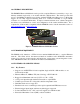
There are two M-module mounting locations on the EM405D. Single-wide M-modules may be installed in either or both of the positions. A double-wide M-module will occupy both positions. The EM405D configuration is illustrated in Figure 3. LED POWER FUSE PWR CNV FUSE FUSE SWITCH CAP MODULE B CAP FAN CAP TMP OSC BUF BUF BUF SIG PROT DSUB CPLD MODULE A uC ETHERNET CPLD PRG LED uC PRG Figure 3. M/MA Configuration Diagram CAUTION: M-module connectors are NOT keyed.
3.0 FUNCTIONAL DESCRIPTION 3.1 GENERAL The EM405D provides a mechanical and electrical interface between an Ethernet bus and up to two M-modules. It utilizes an embedded microcontroller to provide buffering and command translation between the Ethernet interface and the M-modules. A simplified functional block diagram is shown in Figure 4.
3.1.3 M-module Interface The M-module interface provides the mechanism for the microcontroller to access the Mmodules. It is implemented using programmable logic that emulates a bridge between the microcontroller and the M-module bus. The logic also provides trigger configuration and control. 3.1.4 Power Conversion The +12V input power is converted to the +3.3V power required by the carrier and the +5V, +12V, and -12V power required by the M-modules. The input power can be supplied through the 2.
3.3 FRONT PANEL The front panel of the EM405D contains two openings for access to the M-modules’ front panel connections and three LED indicators as shown in Figure 6. As mandated by the M-module specification, each M-module should provide a front panel connector containing the M-module I/O signals. The two openings on the EM405D’s front panel provide access to these connectors.
10
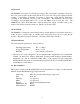
4.0 OPERATING INSTRUCTIONS 4.1 GENERAL The EM405D is controlled through the Ethernet interface using the TCP/IP protocol to carry a simple command structure to the module. The carrier contains a set of software controlled registers that allow the user to request status from the carrier, identify the carrier, and configure the carrier. All other M/MA controls are dependent on the specific M-module(s) that reside on the carrier. 4.
RECOMMENDATION The EM405D is an embedded device without an input device or display that can be used to determine the current configuration of the device. This can cause difficulties in determining at what IP address to access the module. For this reason, it is highly recommended, but not required, that the EM405D be configured to use a static IP address. 4.2.2 Subnet Mask The subnet mask defines the number of bits that are taken from the IP address to refer to the given network subsection.
of other tasks. In ad-hoc mode, wireless devices may communicate directly with each other and an access point is not needed. In this case, all devices on the network must be configured to use ad-hoc mode. The default network mode is: infrastructure. SSID: The Set Service Identifier (SSID) is a name given to a wireless access point to identify the access point on a wireless network. Most access points can be configured to periodically broadcast the SSID or to keep it private.
4.2.6.1 Wed-based Configuration To use the wed-based interface to configure the wired EM405D, open a Java enabled web browser and enter the device’s IP address as the web address to open. This will download and run a Java applet from the device allowing the user to make changes to the devices configuration. Navigate through the pages of the web interface making the necessary changes to the configuration. When finished, click on the “Update Settings” button to apply the changes.
always starting with 00-20-4A identifying the manufacturer of the device. The last three parts of the number are unique to each unit. Example: 00-20-4A-11-68-4C 2) Create an entry in the host computer’s ARP table using the intended temporary IP address and the hardware address of the EM405D found in step 1.
4.2.7.1 Wed-based Configuration To use the wed-based interface to configure the wireless EM405D, open a web browser and enter the device’s IP address as the web address to open. This will launch the main web page of the configuration utility. Navigate through the pages of the web interface making the necessary changes to the configuration. When finished making changes in any given section, click on that pages “Apply” button to apply the changes.
The defaults that are restored using the above procedure are those set by the manufacturer of the Ethernet device and not by C&H Technologies, Inc. The default settings of the carrier as received from the factory at C&H are different in several key areas. The user must manually return these settings to the default as set by C&H in order for the carrier to operate properly. Refer to APPENDIX C or details on the factory default settings as received from C&H Technologies, Inc. 4.
Successful (0x00): The command completed successfully without error. Invalid Command (0x01): The first byte received was not a valid command-id value from the list in Table I. Invalid Parameter (0x02): The EM405D received a valid command however the command could not be completed because one of the command parameters was invalid or out of range. Refer to the description of each individual command for parameter details.
4.3.2 Write Data command The Write Data command writes data to an EM405D control register or to a register residing on an M-module. The command consists of seven bytes including the command-id, the module to which the data should be written, an address space selector, the access width, the address, and two data bytes. The return value consists of a single status byte.
Example (values shown hex): To read the Device Identification Register on the EM405D, send the following command: 4.3.4 Command: Send: cd md as ws ad 30 00 00 02 02 Receive: 0F DB 00 (if successful) Block Access The EM405D provides a flexible block access feature that can be used to significantly improve data throughput. Both a block read and a block write command is implemented. The flexibility of the bock access feature is in the command protocol.
Example 4: Read 32 words starting at address 0x0 followed by 32 words starting at address 0x80 starting address = 0x0 block size = 32 number of blocks = 2 address increment = 128 4.3.4.1 Block Write command The Block Write command writes a block of data to an M-module. A maximum of 1024 bytes can be written in a single command.
4.3.4.2 Block Read command The Block Read command reads a block of data from an M-module. Unlike the block write command, block read does not have a restriction on the number of bytes that can be read with a single command. The number of bytes read in any given command is equal to: number of bytes = number of blocks * block size * word size The block read command consists of nine command bytes.
4.3.5 EM405D Configuration/Status Registers The EM405D contains a set of registers that are used to identify the carrier, configure the carrier, and retrieve status from the carrier. These registers are independent of the M-modules residing on the board. Table III summarizes the register map. Bit level details of each register can be found in Figure 7. These registers are accessed using the Read Data and Write Data commands with the module field of the command set to ‘0’. Table III.
Reg. 00 Byte Bit 15 Write RERR Read RERR Reset Error & Manufacturer Identification 1 14 13 12 0 0 0 0 11 10 9 8 7 6 5 4 3 2 1 0 Read Only MID RERR Reset Error (writing a 1 clears the error condition) 1 MID Manufacturer ID (always FC116 - C&H) Notes: 1. This bit is set if a command error occurs. If an error exists, only reads or writes to this register are allowed. The RERR bit must be cleared by writing a 1 to this bit before normal command operation will resume. See 4.3.
Reg. 08 Byte Bit 15 Write RSTB Read RSTB Reset & Trigger Control 9 8 14 13 12 11 RSTA RSTA TLVL TLVL TIMP TIMP BTBD BTBD RSTB RSTA TLVL TIMP BTBD BTBM BTAD BTAM ATBD ATBM ATAD ATAM 10 9 BTBM BTBM 8 7 BTAD BTAD 6 BTAM BTAM 5 4 ATBD ATBD 3 ATBM ATBM 2 1 ATAD ATAD 0 ATAM ATAM Reset M-module B (0 = normal, 1 = reset) 1 Reset M-module A (0 = normal, 1 = reset) 1 External Trigger Input Threshold Level (0 = +2.5V, 1 = +1.
4.4 CONTROLLING THE TRIGGERS The carrier implements flexible trigger control capabilities providing the user with many options for using triggers. Each M-module can support two trigger lines (labeled A & B) which can be mapped to one of two external trigger lines (one input and one output) available on the carrier or to the trigger lines of the adjacent M-module. The carrier’s external trigger lines can be accessed at the 9-pin DSUB connector on the back panel of the EM405D.
The function of each M-module trigger line is fully dependent upon the M-module. Refer to the particular M-module’s documentation for further details. 4.5 FAN AND TEMPERATURE CONTROL The EM405D contains an on-board temperature sensor placed near the M-module positions. The current temperature inside the EM405D case can be determined by reading the Fan & Temperature Control register of the EM405D. The TEMP field inside this register represents the current temperature as read by the temperature sensor.
28
APPENDIX A - CONNECTORS 1 2 6 3 7 PIN 1 2 3 4 5 6 7 8 9 4 8 5 9 DESCRIPTION +12V INPUT +12V INPUT +12V INPUT TRIGGER OUT TRIGGER IN GND GND GND GND Figure A-1.
A-2
APPENDIX B – WIRED ETHERNET DEFAULT SETTINGS The Ethernet interface device on the wired version of the EM405D contains many configurable settings that allow it to be used in a large number of applications. Many of these settings must be set to certain values in order for the EM405D to operate normally. Other settings are not applicable to the EM405D. When the user tries to configure the network settings via the webinterface or the telnet interface, he/she will see options to change many of these settings.
Table B-1. Ethernet Interface Default Settings.
Table B-1. Ethernet Interface Default Settings. (continued) Email Notification Domain Name Mail Server Recipients Triggers Unit Name blank 0.0.0.
B-4
APPENDIX C – WIRELESS ETHERNET (Wi-Fi) DEFAULT SETTINGS The Ethernet interface device on the Wireless version of the EM405D contains many configurable settings that allow it to be used in a large number of applications. Many of these settings must be set to certain values in order for the EM405D to operate normally. Other settings are not applicable to the EM405D. When the user tries to configure the network settings via the web-interface, he/she will see options to change many of these settings.
Table C-1. Wireless Ethernet Configuration Default Settings.
Table C-1. Wireless Ethernet Configuration Default Settings.
C-4
N O T E S:
.
READER'S COMMENT FORM Your comments assist us in improving the usefulness of C&H's publications; they are an important part of the inputs used for revision. C&H Technologies, Inc. may use and distribute any of the information that you supply in any way that it believes to be appropriate without incurring any obligation whatsoever. You may, of course, continue to use the information, which you supply.
INSTRUCTIONS In its continuing effort to improve documentation, C&H Technologies, Inc. provides this form for use in submitting any comments or suggestions that the user may have. This form may be detached, folded along the lines indicated, taped along the loose edge (DO NOT STAPLE), and mailed. Please try to be as specific as possible and reference applicable sections of the manual or drawings if appropriate.