
Inc. Active Module Carrier User's Manual

8
1.2 SPECIFICATIONS OF EQUIPMENT
1.2.1 Key Features
Provides direct access to the VME module’s front panel I/O connections
Supplies buffered data, address, interrupt, and trigger lines (ECL and TTL)
Includes direct SUMBUS connections, as well as a prototyping area with fused ±12V
power supplies for buffered SUMBUS connections (jumper selectable)
Conforms with VMEbus/VXIbus driving and loading specifications
Provides VME64 +3.3V supplies (-0001, -0003, and -0004 versions only)
Mates with VXI, VME, and VME64 rear connectors
1.2.2 Electrical
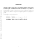
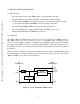
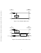
The -0001, -0003, and -0004 versions provide +3.3V power to the P1 row D VME64 extension.
The -0002 version does not provide +3.3V power. A simplified power schematic for each
version is shown in Figure 2, Figure 3, and Figure 4. Excluding the +3.3V supply, the VX402C-
64 only requires 300mA of +5V power from the VXI backplane. This power requirement is for
the VX402C-64 alone. Any attached module will increase this value by the amount specified in
its data sheet.
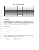
Table I provides a summary of the supply capabilities of each version. The table assumes that
the VXI backplane is capable providing 1.2A on each of the seven +5V power pins. For versions
-0003 and -0004, 1.2A on the -24V and +24V pins.
Figure 2. Power Schematic (-0001 version)
VXI
BACKPLANE
+5V
+3.3V
+5V
VME64
CONNECTORS
GND
GND
(7 PINS)
(7 PINS)
(10 PINS)
INTERNAL
LOGIC
DC-DC
CONVERTER
C&H Technologies, Inc. <> 445 Round Rock West Drive <> Round Rock, TX 78681 <> www.chtech.com