C&H Technologies, Inc. <> 445 Round Rock West Drive <> Round Rock, TX 78681 <> www.chtech.
COPYRIGHT C&H Technologies, Inc. <> 445 Round Rock West Drive <> Round Rock, TX 78681 <> www.chtech.com C&H Technologies, Inc. (C&H) provides this manual "as is" without warranty of any kind, either expressed or implied, including but not limited to the implied warranties of merchantability and fitness for a particular purpose. C&H may make improvements and/or changes in the product(s) and/or program(s) described in this manual at any time and without notice.
C&H Technologies, Inc. <> 445 Round Rock West Drive <> Round Rock, TX 78681 <> www.chtech.com AMENDMENT NOTICE C&H Technologies, Inc. makes every attempt to provide up-to-date manuals with the associated equipment. Occasionally, changes are made to the equipment wherein it is necessary to provide amendments to the manual. If any amendments are provided for this manual they are printed on colored paper and will be provided with the module and manual. Manual updates may also be found on out web site at www.
INTRODUCTION C&H Technologies, Inc. <> 445 Round Rock West Drive <> Round Rock, TX 78681 <> www.chtech.com This manual describes the operation and use of the C&H Model VX402C-64 VXI Active Carrier Module (Part Number 11028500 Revision B or higher). This VXI module is one of a number of test and data acquisition/control modules in the VME and VXI format provided by C&H.
C&H Technologies, Inc. <> 445 Round Rock West Drive <> Round Rock, TX 78681 <> www.chtech.com TABLE OF CONTENTS 1.0 GENERAL DESCRIPTION ..................................................................................................... 7 1.1 PURPOSE OF EQUIPMENT........................................................................................ 7 1.2 SPECIFICATIONS OF EQUIPMENT.......................................................................... 8 1.2.1 Key Features .............................
C&H Technologies, Inc. <> 445 Round Rock West Drive <> Round Rock, TX 78681 <> www.chtech.com LIST OF FIGURES Figure 1. Front Panel and Top View (Top Shield Not Shown) .......................................................7 Figure 2. Power Schematic (-0001 version)....................................................................................8 Figure 3. Power Schematic (-0002 version)....................................................................................9 Figure 4.
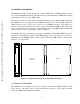
1.0 GENERAL DESCRIPTION The carrier provides an actively-buffered electrical interface for the standard VME bus signals. The VX402C-64 does not support the full VME64 extension bus; however, -0001, -0003, and -0004 versions provide +3.3V power to the P1 row D VME64 extension. The adapter also features a VXI C-size mechanical enclosure to support and shield the VME module.
1.2 SPECIFICATIONS OF EQUIPMENT 1.2.1 Key Features Provides direct access to the VME module’s front panel I/O connections C&H Technologies, Inc. <> 445 Round Rock West Drive <> Round Rock, TX 78681 <> www.chtech.
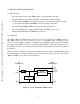
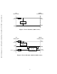
C&H Technologies, Inc. <> 445 Round Rock West Drive <> Round Rock, TX 78681 <> www.chtech.com VXI BACKPLANE VME64 CONNECTORS +5V +5V (7 PINS) (7 PINS) INTERNAL LOGIC GND GND Figure 3. Power Schematic (-0002 version) VXI BACKPLANE VME64 CONNECTORS +5V +5V (7 PINS) (7 PINS) INTERNAL LOGIC GND +24V or -24V GND ISOLATED DC-DC CONVERTER (1 PIN) OUTOUT+ +3.3V (10 PINS) Figure 4.
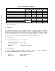
C&H Technologies, Inc. <> 445 Round Rock West Drive <> Round Rock, TX 78681 <> www.chtech.com Table I. Power Supply Capabilities VXI +5V Supply Capability VXI +24V Supply Capability VXI -24V Supply Capability Internal +5V Power Consumption Remaining +5V Power Available +3.3V Converter Efficiency +5V Power Available to VME Module +3.3V Power Available to VME Module -0001 42.0W not used not used 1.5W 40.5W 92% 37W Total VX402C-64 Version -0002 -0003 42.0W 42.0W not used not used not used 29W 1.5W 1.5W 40.
2.0 INSTALLATION C&H Technologies, Inc. <> 445 Round Rock West Drive <> Round Rock, TX 78681 <> www.chtech.com 2.1 UNPACKING AND INSPECTION In most cases the VX402C-64 is individually sealed and packaged for shipment. Verify that there has been no damage to the shipping container. If damage exists then the container should be retained as it will provide evidence of carrier caused problems. Such problems should be reported to the carrier immediately as well as to C&H.
C&H Technologies, Inc. <> 445 Round Rock West Drive <> Round Rock, TX 78681 <> www.chtech.
3.0 FUNCTIONAL DESCRIPTION C&H Technologies, Inc. <> 445 Round Rock West Drive <> Round Rock, TX 78681 <> www.chtech.com 3.1 GENERAL VX402C-64 is a general purpose carrier module for VXI C-Size chasses. The module provides actively buffered signals, which meet all VME specifications, to the VME module. A functional block diagram is shown in Figure 5. P1 J1 Trigger Buffer Interrupt Buffer To VME Module Address Buffer P2 J2 Data Buffer Pass-Through Connectors Trigger Buffer Figure 5.
3.2 TRIGGERS C&H Technologies, Inc. <> 445 Round Rock West Drive <> Round Rock, TX 78681 <> www.chtech.com Both ECL and TTL triggers are supplied through the VX402C-64. There are switches on the carrier which are used to set the direction of the triggers (to the backplane and from the backplane). 3.2.1 TTL TRIGGERS Eight TTL Trigger lines pass through the VX402C-64 to the front panel: TTLTRG0-7. Each trigger line may be set as an input or output trigger.
3.2.2 ECL TRIGGERS C&H Technologies, Inc. <> 445 Round Rock West Drive <> Round Rock, TX 78681 <> www.chtech.com The VX402C-64 supports two ECL Trigger lines: ECLTRG0-1. Each trigger line may be set as an input or output trigger. The trigger direction is set using switch S2 which can be seen in Figure 7. The trigger directions are clearly marked on the board itself. J1 P1 S2 ECLTRG0 ECLTRG1 1 ON S2 TO BACKPLANE FROM BACKPLANE ECLTRG J2 P2 Figure 7. ECL Trigger Direction 3.3 CONNECTORS 3.3.
C&H Technologies, Inc. <> 445 Round Rock West Drive <> Round Rock, TX 78681 <> www.chtech.com 3.3.3 PASS-THROUGH CONNECTORS One major difference between the VME bus and the VXI bus is that the outer rows of the P2 connector are not defined on the VME bus and they are defined on the VXI bus. For this reason, the VX402C-64 Active Module Carrier provides a Pass-Through Connector system that be used to optionally connect or not connect the VME P2 Rows A & C signals to the VXI P2 Rows A & C signals.
C&H Technologies, Inc. <> 445 Round Rock West Drive <> Round Rock, TX 78681 <> www.chtech.com A one-to-one cable that connects Pin 1 (C32) on the VXI side to Pin 1 (C32) on the VME side, and so on, could only be used if the VME module was designed to meet all of the VXI bus specifications for these pins. If the installed VME module can not handle -24V, +24V, -5.2V or any other signal on the corresponding pin, then a one-to-one cable can not be used.
3.4 SUMBUS CONFIGURATION C&H Technologies, Inc. <> 445 Round Rock West Drive <> Round Rock, TX 78681 <> www.chtech.com The VX402C-64 provides a direct connection of the SUMBUS signal through the pass-through connector to the front connectors. The board also has a prototyping area so that the user can hardwire a custom buffer for the SUMBUS signal. 3.4.1 SUMBUS CUSTOM AREA The SUMBUS custom area consists of a prototyping grid, ±12V supplies, and two jumpers for configuring the signal.
3.4.2 SUMBUS JUMPER SETTINGS C&H Technologies, Inc. <> 445 Round Rock West Drive <> Round Rock, TX 78681 <> www.chtech.com In order to use the SUMBUS signal, the jumpers J11 and J12 must be configured properly. The three different settings for the jumpers can be seen in Figure 10. The SUMBUS signal can be connected directly to the front panel (A), connected through the prototyping area (B), or disconnected (C). The pass-through connector must be installed for the SUMBUS signal to route to the front panel.
C&H Technologies, Inc. <> 445 Round Rock West Drive <> Round Rock, TX 78681 <> www.chtech.
4.0 OPERATING INSTRUCTIONS C&H Technologies, Inc. <> 445 Round Rock West Drive <> Round Rock, TX 78681 <> www.chtech.com While the VX402C-64 is an active carrier, it is designed to be completely transparent to the host interface. For this reason, the VME module can be accessed as if it were plugged directly into the host backplane. In order to operate the VME module, first set up the hardware configurations on the VX402C-64. Then set the necessary trigger directions using the switches.
C&H Technologies, Inc. <> 445 Round Rock West Drive <> Round Rock, TX 78681 <> www.chtech.
C&H Technologies, Inc. <> 445 Round Rock West Drive <> Round Rock, TX 78681 <> www.chtech.
C&H Technologies, Inc. <> 445 Round Rock West Drive <> Round Rock, TX 78681 <> www.chtech.com PIN 1 2 3 4 5 6 7 8 9 10 11 12 13 14 15 16 17 18 19 20 21 22 23 24 25 26 27 28 29 30 31 32 C CLK10+ CLK10GND -5.2V LBUSC00 LBUSC01 GND LBUSC02 LBUSC03 GND LBUSC04 LBUSC05 -2V LBUSC06 LBUSC07 GND LBUSC08 LBUSC09 -5.
C&H Technologies, Inc. <> 445 Round Rock West Drive <> Round Rock, TX 78681 <> www.chtech.com PIN 1 2 3 4 5 6 7 8 9 10 11 12 13 14 15 16 17 18 19 20 21 22 23 24 25 26 27 28 29 30 31 32 D GND +3.3V +3.3V +3.3V +3.3V +3.3V +3.3V +3.3V +3.3V +3.3V +3.
C&H Technologies, Inc. <> 445 Round Rock West Drive <> Round Rock, TX 78681 <> www.chtech.com PIN 1 2 3 4 5 6 7 8 9 10 11 12 13 14 15 16 17 18 19 20 21 22 23 24 25 26 27 28 29 30 31 32 D GND - C CLK10+n CLK10-n GND14 -5.2V5 LBUSC00n LBUSC01n GND12 LBUSC02n LBUSC03n GND10 LBUSC04n LBUSC05n -2V1 LBUSC06n LBUSC07n GND08 LBUSC08n LBUSC09n -5.
C&H Technologies, Inc. <> 445 Round Rock West Drive <> Round Rock, TX 78681 <> www.chtech.com PIN 1 3 5 7 9 11 13 15 17 19 21 23 25 27 29 31 33 35 37 39 41 43 45 47 49 51 53 55 57 59 61 63 TO FRONT CONNECTOR J2 PIN -24Vn 2 BSUMBUSn +24Vn 4 GND01 GND02 6 MODIDn RSV3n 8 RSV2n GND03 10 GND04 BTTLTRG7*n 12 BTTLTRG6*n BTTLTRG5*n 14 BTTLTRG4*n GND05 16 +5Vn BTTLTRG3*n 18 BTTLTRG2*n BTTLTRG1*n 20 BTTLTRG0*n GND06 22 GND07 LBUSC11n 24 LBUSA11n LBUSC10n 26 LBUSA10n -5.2V1 28 -5.
A-6 C&H Technologies, Inc. <> 445 Round Rock West Drive <> Round Rock, TX 78681 <> www.chtech.
C&H Technologies, Inc. <> 445 Round Rock West Drive <> Round Rock, TX 78681 <> www.chtech.
C&H Technologies, Inc. <> 445 Round Rock West Drive <> Round Rock, TX 78681 <> www.chtech.
READER'S COMMENT FORM C&H Technologies, Inc. <> 445 Round Rock West Drive <> Round Rock, TX 78681 <> www.chtech.com Your comments assist us in improving the usefulness of C&H's publications; they are an important part of the inputs used for revision. C&H Technologies, Inc. may use and distribute any of the information that you supply in any way that it believes to be appropriate without incurring any obligation whatsoever. You may, of course, continue to use the information which you supply.
C&H Technologies, Inc. <> 445 Round Rock West Drive <> Round Rock, TX 78681 <> www.chtech.com INSTRUCTIONS In its continuing effort to improve documentation, C&H Technologies, Inc. provides this form for use in submitting any comments or suggestions that the user may have. This form may be detached, folded along the lines indicated, taped along the loose edge (DO NOT STAPLE), and mailed. Please try to be as specific as possible and reference applicable sections of the manual or drawings if appropriate.