
User Manual

VI. -- FUNCTION
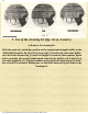
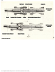
1. Bolt function (fig. 15).
In the locked bolt position, the position of the different parts are as indicated in
figure 15 a). The rollers, forced by the inclined flanks of the firing pin locking
piece, are pushed out of the windows of the bolt head and introduce themselves
into the cavities of the trunion.
Once a shot is fired, the pressure of the gasses acts on the rear of the cartridge,
pushing it against the front face of the bolt head, and this force is transmitted to
the rollers, which, in turn, press against the inclined flanks of the firing pin
locking piece, pushing it rearward. The firing pin locking piece drags along
with it the bolt. As a consequence of this movement, the rollers are hidden in
the head of the bolt and the diverse parts of the system take the disposition
indicated in fig. 15 b), where the separation between the support and the head
of the bolt can be seen. From this point forward, the entire system moves
rearward freely, due to the impulse gained by the mass of the bolt carrier,
overcoming the action of the recoil spring. Finally, the energy stored by this
spring makes the bolt carrier move forward again and come back to the
position in figure 15 a).
As can be seen from the previous explanation, the weapon remains locked until
the bolt support has moved a short distance. The time that it takes for the bolt
support to move this distance is much greater than what it takes for the bullet
to travel through the barrel.
27
file:///C|/WINDOWS/Desktop/version 2 cetme/27.htm [3/23/2002 9:01:16 PM]