index file:///C|/WINDOWS/Desktop/version 2 cetme/coverpage.
intro Introduction Final Version 2.
1 Abbreviated Description and Use Of CETME Assault Rifle, Model C 7.62 x 51 mm. Caliber Center for the Technical Study of Special Materials Padilla, 46 - Madrid Spain file:///C|/WINDOWS/Desktop/version 2 cetme/1.
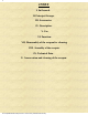
2 INDEX I. In General. II. Principal Groups. III. Accessories. IV. Description. V. Use. VI. Function. VII. Disassembly of the weapon for cleaning. VIII. Assembly of the weapon. IX. Technical Data. X. Conservation and cleaning of the weapon. file:///C|/WINDOWS/Desktop/version 2 cetme/2.
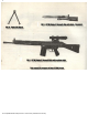
3 I. IN GENERAL The CETME rifle, caliber 7.62 x 51 mm., is a weapon developed using the most modern fabrication methods. It may be fired a round at a time with automatic loading, or fired automatically. Its functioning system is mass recoil with semi-rigid locking and a fixed barrel. It has a flash suppresser screwed on to the mouth of the barrel which permits rifle grenades to be fired with no other device required. The feeding is accomplished with a magazine of 20 cartridges.
4 file:///C|/WINDOWS/Desktop/version 2 cetme/4.
5 file:///C|/WINDOWS/Desktop/version 2 cetme/5.
6 II. Principle Groups 1. Barrel, receiver, cocking mechanism, sights and handguard (eventually bipods). 2. Bolt. 3. Grip with trigger mechanism. 4. Buttstock with recoil spring and buffer. III. Accessories 1. Magazine. 2. Sling. 3. Attachment for firing blank cartridges. 4. Cleaning kit. 5. Muzzle cover and protective bag. 6. Magazine loader. 7. Knife-Bayonet. 8. Optical Sight 9. Telescopic bipod model BR. file:///C|/WINDOWS/Desktop/version 2 cetme/6.
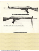
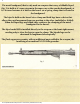
7 IV. Description 1. Barrel, receiver, cocking mechanism, sights and handguard (eventually bipods) (fig. 5). The barrel is fixed, at its rear portion, to the trunion block. At its fore end it has a threaded flash suppresser. The receiver is fabricated from a sheet metal stamping. At its fore end it is joined, by welding, to the trunion block. At the rear it is joined to the buttstock by two crosspins. On its lower section it has the magazine well, and to this part the grip assembly is joined by a crosspin.
8 The metal handguard, that is only used on weapons that carry a foldable bipod (fig. 2) is held at it's rear extreme in the same way as the wooden handguard; at it's forward extreme it is held on the barrel via a spring clamp that is riveted to the handguard. The bipod is held on the barrel via a clamp and both legs have a device that allows the rapid movement from one position to the other (unfolded or folded).
9 The bolt assembly is found in the interior of the receiver where it travels during the locking, and unlocking sequence of the weapon. It's mission is to feed, lock, and extract the case after it is fired. It consists of the following parts: Bolt carrier with recoil spring support tube. Bolt head with locking roller, extractor, and extractor spring. Firing pin holder. Firing pin spring. Firing pin. file:///C|/WINDOWS/Desktop/version 2 cetme/9.
10 file:///C|/WINDOWS/Desktop/version 2 cetme/10.
11 3. Grip with trigger mechanism (fig. 7) The grip is joined at its front end to the receiver via a crosspin that serves as its rotation point. At the rear end it is held between the receiver and the buttstock holder. The grip holds in its upper part the trigger mechanism, that is comprised of the following principal parts: Trigger. Disconnector assembly. Hammer. Safety lever. Ejector. These parts, with their crosspins and corresponding springs, are mounted in the trigger pack (b).
12 file:///C|/WINDOWS/Desktop/version 2 cetme/12.
13 4. Buttstock assembly with recoil spring and buffer. (fig. 8) The buttstock is made of tropical walnut, ("nogal"). It has a pad of hardened rubber, with metal reinforcement. At the front end of the buttstock assembly is the buttstock housing, which is held to the grip assembly via two crosspins. The recoil spring support tube is riveted to the buttstock housing. The end of the recoil spring is retained by a bushing that is held at the end of the tube by a crosspin.
14 file:///C|/WINDOWS/Desktop/version 2 cetme/14.
15 DESCRIPTION OF THE ACCESSORIES 1. Magazine. Is made of stamped sheetmetal. Two types are fabricated: the normal, with a capacity of 20 cartridges, and another of 5 cartridges for garrison duty. 2. Sling. Is made of web material, with a clip at one of its extremes and a buckle that permits regulation of its length. 3. Blank firing adapter. It is used in substitution of the flash suppresser. It can be regulated, to allow firing blank cartridges of different strengths. 4. Cleaning Kit.
16 file:///C|/WINDOWS/Desktop/version 2 cetme/16.
17 6. Magazine loader. (fig. 10) Consists of a sheetmetal box (1) with a cover (2), open at its two extremes, in which at one extreme the magazine is latched (3). A pusher (4), also made of sheetmetal, slides within the interior of the box. Filled with cartridges, as one can see in view a) of the picture, and the box closed, holding the cover with one hand and pressing on the pusher with the other, as indicated in view b), the magazine is filled rapidly and comfortably. 7. Knife-Bayonet.
18 file:///C|/WINDOWS/Desktop/version 2 cetme/18.
19 V. HANDLING 1. Insertion and removal of the magazine (fig. 11). The magazine is introduced in the weapons magazine well without the need to actuate any mechanism (fig. 11 a). The retaining lip automatically locks the magazine in securely. To remove the magazine, at the same time that it is gripped by the hand to remove it, the release lever is pressed forward, as indicated in figure (11 b). The magazine can also be removed by pressing on the magazine release button (2).
20 file:///C|/WINDOWS/Desktop/version 2 cetme/20.
21 2. Load the weapon (fig. 12). With a full magazine inserted and locked in its well, move the safety to the <> or <> (depending on how you wish to fire. one shot at a time or in bursts), pull back the Cocking Lever completely, and let it go forward with full force, so that the bolt can lock forward, leaving the weapon locked, loaded and ready to fire. file:///C|/WINDOWS/Desktop/version 2 cetme/21.
22 file:///C|/WINDOWS/Desktop/version 2 cetme/22.
23 3. Secure the weapon (fig. 13). Once the weapon is locked and loaded, if you wish to secure it, place the safety in the <> position. If you wish to leave the weapon secured but with an open bolt, place the safety in any of the positions <> or <>, pull the cocking lever rearward and, sliding it to the right, allow it to catch in the cutout of the guide tube. Once latched, place the safety in the <> position. 4. Firing. One shot at a time: Place the safety in the <> position.
24 5. Use of the cleaning kit (fig. 14) (a, b and c). a) Remove the cleaning kit.
25 b) Cleaning the chamber. Pull the cocking lever to the rear and leave it in the retained position. Screw the chamber brush on the articulated handle and clean the chamber in the manner indicated in figure 14 b, passing the brush various times over the chamber, through the ejection port. file:///C|/WINDOWS/Desktop/version 2 cetme/25.
26 c) Cleaning the barrel. With the bolt assembly locked open, introduce the nylon brush through the muzzle of the weapon and pull it out through the ejection port (fig. 14 c). Repeat this operation two or three times. The last time, lightly impregnate the brush with oil, with one of the oil capsules, use the oil to grease the bolt rollers.
27 VI. -- FUNCTION 1. Bolt function (fig. 15). In the locked bolt position, the position of the different parts are as indicated in figure 15 a). The rollers, forced by the inclined flanks of the firing pin locking piece, are pushed out of the windows of the bolt head and introduce themselves into the cavities of the trunion.
28 file:///C|/WINDOWS/Desktop/version 2 cetme/28.
29 2. Firing mechanism function (fig. 16). a) One shot at a time. With the safety in the <> position, the rear end of the disconnector (3) fits into a slot in the safety shaft (6) and the forward extreme protrudes. When the trigger is pulled (1), the firing lever (2) releases the hammer (4), that due to the action of its spring hits the firing pin and produces the shot. The bolt assembly, during its rearward travel, mounts the hammer (4), that is then held by the front hook of the disconnector (3).
30 c) On safe. With the safety in the <> position, the shaft of the safety (6) blocks the firing lever (2) impeding its rotation and, the release of the hammer. file:///C|/WINDOWS/Desktop/version 2 cetme/30.
31 VII.-- DISASSEMBLY OF THE WEAPON FOR CLEANING a) Remove the magazine if it is still inserted in the weapon. b) Be sure that there are no cartridges in the chamber. To do this, pull the cocking lever to the rear and, check that the chamber is empty, let go of the lever so that the bolt assembly moves forward. c) Remove the two buttstock retaining pins, introducing them into the two drilled holes provided for them in the buttstock. d) Remove the buttstock assembly with the recoil spring (fig. 17).
32 file:///C|/WINDOWS/Desktop/version 2 cetme/32.
33 g) Disassembly of the bolt assembly: Press down on the head in a longitudinal direction, until it hits against the back of the bolt carrier; rotate the head 180° in a counterclockwise direction and remove it (fig. 18 a). Rotate the firing-pin locking piece, and remove it (fig. 18 b). Remove the firing-pin and its spring. h) Disassembly of the firing mechanism: -- It is not necessary to perform this operation during the normal cleaning of the weapon.
34 file:///C|/WINDOWS/Desktop/version 2 cetme/34.
35 VIII. -- ASSEMBLY OF THE WEAPON a) Assemble the bolt assembly following the reverse order as described for its disassembly. Separate the bolt head from the support so as to hide the rollers; for this, the best method is to introduce the bolt assembly backwards into the rear end of the receiver and hit it lightly. b) Introduce the bolt assembly into the receiver in its correct position and let it slide in until it is at its most forward position. (fig. 19).
36 file:///C|/WINDOWS/Desktop/version 2 cetme/36.
37 IX.-- TECHNICAL DATA Caliber........................................................................ 7.62 mm. - NATO .308 Length of the weapon................................................. 1.015 mm. - 39.96 inches Weight of the weapon with wooden handguards....... 4.2 kg. - 9.25 lbs Weight with bipod and metal handguards.................. 4.5 kg. - 9.92lbs Length of the barrel.................................................... 450 mm. - 17.71 inches Travel of the rifling.............................
38 X.-- CONSERVATION AND CLEANING OF THE WEAPON Generally.-- Before putting an Assault Rifle into service the cosmoline, or grease in which it comes from the factory for conservation must be removed. To this effect, it must be broken down and its parts washed with benzene or petroleum and, once it is very clean, a lightly lubricated bore brush should be passed through the throat and chamber. The Assault Rifle will be maintained in perfect condition through scrupulous cleaning.
39 When it is necessary to clean the firing mechanism, it should be done without removing it from the pistol grip, as this operation should only be performed by a Master Armorer. Lubrication. Lubrication is an indespensible compliment to cleaning, to conserve the weapon, and keep it functioning correctly. Lubrication is necessary to keep the parts from rusting. It is necessary on the outer surfaces, and on those that are exposed to friction or movement.
40 GREASES AND OILS The following greases and oils will be used for lubricating: Lubricant: Anticorrosive lubricating oil, medium type, as per standard MIL - L - 3150 (ET 45 or SHELL-TURBO OIL 37). Conservation Grease: General use anticorrosive grease, as per standard MIL G - 10924 B (SHELL-GREASE S - 6751). file:///C|/WINDOWS/Desktop/version 2 cetme/40.
41 MOST FREQUENT INTERRUPTIONS AND WAYS TO FIX THEM The most frequent interruptions in the functioning of the Assault Rifle are due to the untrained handling of the weapon and more frequently due to cartridges or magazines defective because of abuse. Every time that firing is interrupted involuntarily you should wait for 15 seconds before trying to fix the defect. Take into account that the first operation that should be performed in any case is to remove the magazine.
The following table details the failures, causes that motivate them and ways to fix them. FAILURE Failure to fire. MOTIVATING CAUSE a) Defective cartridge due to manufacture, humidity of the primer or powder. b) Firing pin is broken. c) Due to a foreign body or a dirty firing pin chamber. d) Bent extractor HOW TO FIX a) Remove the magazine. Verify the mark of the firing pin on the primer. Introduce an unmarked cartridge directly into the chamber and fire. Repeat the operation with other cartridges.
Failure to feed automatically 1) The cartridge is caught between the bolt 1) a) Remove the magazine and tap the rear and the loading port. end of it against the palm of the hand so as to correct the positioning of the cartridges. a) Due to incorrect loading of cartridges in If this does not solve the problem, empty the magazine or the charging lever spring the magazine and reload it. is stuck. b) Change the magazine. b) Defective magazine. c) Replace the spring.
BALLISTICS TABLE OF THE SPANISH ASSAULT RIFLE 7.62 MM. Ammo: Nato Weight of the bullet: 9.4 grams Barometric Pressure: 750 mm. Hg. Vo = 780 m/sec. Temperature 15° C. Io = 1.04 Kg seg. (impulso) Higrometric State: 50 % Range in meters ANGLES Of projection in thousands Duration of the trajectory in seconds Elements of the vertices of the trajectory. Remaining velocity in m/sec.
44 file:///C|/WINDOWS/Desktop/version 2 cetme/44.