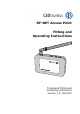
RF-NET Access Point Fitting and Operating Instructions Translated fitting and operating instructions version 1.
Preface Preface These Fitting and Operating Instructions will help you fit and use the RF-NET Access Point (Access Point) as intended, safely, and advantageously. Any person who fits, operates, or disposes of this Access Point must have read and understood the entire contents of these Fitting and Operating Instructions. These Fitting and Operating Instructions should be kept near the Access Point at all times.
Contents Contents Preface .......................................................................... 2 Notes on the layout ....................................................... 2 For your safety .............................................................. 4 Basic safety instructions .......................................... 4 Explanation of the safety notes ....................................... 6 Intended use ................................................................ 7 Remarks ................
For your safety For your safety Basic safety instructions Observe all warnings and notes in these Fitting and Operating Instructions. Always keep these Fitting and Operating Instructions near the Access Point. To prevent danger to life and limb, the following safety instructions must be observed: Danger of explosion Live parts of the Access Point may cause an explosion. Do not use the Access Point in potentially explosive atmospheres.
For your safety Only use the proper tools to open the Access Point. Do not drop the Access Point on the floor, on hard surfaces or on hard objects. Use surge arresters to avoid damage to your Access Point through overvoltage, for example by lightning. Protect the electronic components of the Access Point against water and other liquids. The Access Point contains highly sensitive electronic parts that may be damaged or destroyed through static charges.
For your safety Explanation of the safety notes These Fitting and Operating Instructions include safety notes of the following types: CAUTION CAUTION notes warn against hazards that may result in slight or medium injuries. Notes NOTICE Notes warn against possible property or environmental damage.
For your safety Intended use The Access Point serves to transmit data between locking devices and the control centre of your OMEGA ACTIVE system. Between the Access Point and the locking devices, data are transmitted via 868 MHz radio signals. The connection of the Access Point to the master computer is wired. It is exclusively intended and may only be used for that purpose. Any other use is considered to be improper and may result in property damage or even personal injury.
Introduction Introduction Description The Access Point is part of the OMEGA-system. It establishes the connection between the OMEGA locking devices and the overall control centre via a radio frequency (RF) link. The master computer is a commercial PC with the OMEGA software. The Access Point is connected with the control centre via an RJ45-Ethernet cable (10/100 MBit). The Access Point is thus the network interface of the system.
Introduction Other features of the Access Point: Integrated 868 MHz RF transceiver. The maximum RF range to the locking devices is 25 metres. Power supply of the Access Point with the supplied power pack. No other power supplies are permitted. Two colour LEDs at the Ethernet connection for visual signalization of data traffic. Available accessories for the Access Point: D-LAN™ adapter (System Powerline, to implement IP networks using the 230 V power network).
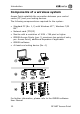
Introduction Components of a wireless system Access Points establish the connection between your control centre (PC) and your locking devices. The following components are required for the system: Standard PC (No. 1, 2) with Windows XP™, Windows 7/32 Bit™ Network card (TCP/IP) Monitor with a resolution of 1024 768 pixel or higher OMEGA Access Points (pos. 3, maximum ten points of entry per Access Point), additional Repeaters if applicable OMEGA software At least one locking device (No. 4).
Introduction OMEGA system components The following shows the components that can be combined within the OMEGA system: These options can be purchased from a CEStronics partner to match your specific requirements. 1 Locking media (optional): Your locking devices can be operated with the following locking media: Transponder key, key fob, card.
Introduction Scope of delivery Before proceeding with fitting and commissioning, please check the contents of the package and the scope of delivery. Check new devices for transport damage and inform your CEStronics partner promptly if any damage is found.
Introduction Unpacking the Access Point Take the Access Point out of the package and remove any packaging material such as film, padding and packaging board. NOTICE Risk of damage to the Access Point. Only use the supplied power pack for the power supply of your Access Point.
Introduction RF ranges Ensure that the permissible RF ranges are observed. Install the devices within the maximum RF range of 25 metres. Checking the range The optional RF-TRACE-MASTER transponder card allows you to check the quality of the radio frequency (RF) link between the OMEGA server and your locking devices. The RF-TRACE-MASTER triggers the following signals of your locking devices: Green LED of your locking cylinder, IES fitting or wall terminal flashes twice: strong RF link.
Introduction If the red and the green LEDs flash alternately or simultaneously, the RF link is weak and should be checked to ensure full functionality and reliability. To verify the quality of the RF link to your locking devices, proceed as follows: Hold the RF-TRACE-MASTER for about two seconds in front of your locking cylinder or wall terminal. The function is performed immediately.
Fitting the Access Point Fitting the Access Point NOTICE If an Access Point fails, your locking devices cannot be reached any more. Make sure that the Access Points are always easily accessible. Make sure that all electrical connections can be separated at any time. NOTICE The Access Point may be damaged if not fitted properly. Only skilled personnel may fit the Access Point. This personnel must have been trained on the product by CEStronics or a CEStronics partner.
Fitting the Access Point When fitting the Access Point, you must ensure the following conditions: Make sure that the power supply and the power supply cable can be plugged in. Make sure that the network cable can be plugged in. The Access Point must not be fitted on metallic surfaces. Always install the Access Point as far away from ground potentials as possible to avoid interference with the radio traffic. The Access Point may not be fitted outdoors. The Access Point is supplied preassembled.
Fitting the Access Point The Access Point must be fitted at an easily accessible location, e.g. near a ceiling or on a wall. A suitable fitting position is for instance above a door frame, at a height of about 2 metres and with as much distance to the nearest object or wall as possible. If the reception is good, install the Access Point with the ports pointing upwards. However, also all other orientations are possible, such as with the antenna pointing to the side or downwards as shown in the figure.
Fitting the Access Point Verify the reception at your locking devices with the optional RF-TRACE-MASTER (see page 14). The orientation of the antenna can be adjusted. As long as the antenna has not yet been screwed in tight, it can be rotated by 360°. After it has been tightened, the antenna can only be aligned vertically and horizontally.
Fitting the Access Point Push the Access Point onto the wall mount. The Access Point only sits properly after it has snapped in the wall mount. Do not yet screw the antenna (1) tight in the antenna base (2) at this point. Do not use any tools for tightening. Establish the required cable connections as described on page 13. Put the Access Point into service.
Fitting the Access Point Check the orientation of the antenna to ensure sufficient effective radiated power. Use the optional RF-TRACE-MASTER to check the effective radiated power (see also note on page 14 "Checking the range"). Orientate the antenna so that your locking devices receive the maximum effective radiated power. As long as the antenna has not yet been screwed in tight, you can rotate it by 360° and align it vertically and horizontally.
Fitting the Access Point If possible, verify the perfect functioning of the Access Point already at this stage: Normal operation Signal location Meaning Is the network connection available? Is the Access Point operative? The two LEDs signal the following conditions: Signal Meaning Green LED, permanent Network connection established (perfect connection to the OMEGA server) Operative Data transmission in progress Red LED, flashing Red LED, flashes short/ flickers Is a data link available? The two LE
Trouble shooting Trouble shooting Symptom Possible cause and remedy No connection to the locking devices can be established. Your connection cables are mechanically damaged or broken. Check the installation for broken wires or faulty connections. Check the continuity of your wires with a suitable instrument (multimeter, ohmmeter). Verify the proper functioning of the plug-in power supply of the Access Point with a suitable instrument (multimeter, ohmmeter).
Trouble shooting Locking devices are outside the radio frequency range of Access Points. Reduce the distance to your locking devices. Verify the quality of the wireless transmission with the optional RFTRACE-Master. The locking devices have no power. Check the power supply of your locking devices. Re-establish the proper power supply of your locking devices. For further information on establishing the power supply, please refer to the operating instructions of your locking devices.
Trouble shooting The OMEGA software is not configured correctly. Your PC does not work properly. Check the software settings as described in the OMEGA User Manual. Check the functioning of the software as described in the OMEGA User Manual. Verify the perfect functioning of your PC. If you are not able to verify the perfect functioning, please contact your PC dealer. Your locking devices do not operate in RF mode. Use the optional RF-INI-MASTER to enable the RF mode of your locking devices.
Maintenance Maintenance Have the Access Point serviced and its perfect functioning verified every six months by CEStronics or by a CEStronics partner only. Spare Parts The Access Point does not require any spare parts for you to change. If you need service, please contact your professional CES partner. Disposal Neither the Access Point, nor any parts of the Access Point may be discarded with the normal household waste.
Technical data Technical data Dimensions: Power supply: Power consumption Connection: Communication frequency: Network protocol: Length: approx. 117 mm, Width: approx. 107 mm, Height: approx. 24 mm 9 V DC Only via the power pack supplied Max. 1,0 W Phonoplug 5.5 2.1 mm 5.5 mm: -, 2.1 mm: + Sending/transmitting 868 MHz TCP/IP RF range: approx. 25 m Temperature rage: Environmental conditions: 0 °C to + 40 °C Not suitable for use in corrosive atmospheres (chlorine, ammonia, lime water).
Glossary Glossary Locking devices Locking devices are locking cylinders electronic shields and wall terminals. If these are operating in RF mode, the Access Point can be linked with them. Reader module The reader module is installed in the outside knob of the locking cylinder or in the wall terminal. It detects your locking media. Master media Cards to program your locking devices. The OMEGA system comprises two types of Master media, the SYSTEMMASTER and the PROGRAM-MASTER.
Notes on the manufacturer's warranty Notes on the manufacturer's warranty As stated in our Standard Terms and Conditions, the manufacturer's warranty does not extend to the following types of damage: damage to outer mechanical parts and damage resulting from normal wear and tear damage as a consequence of external events or influence damage as a consequence of improper operation damage as a consequence of excess voltage damage as a consequence of fire, water or smoke.
C. Ed. Schulte GmbH Zylinderschloßfabrik Friedrichstraße 243 D-42551 Velbert +49 (0)2051-204-0 +49 (0)2051-204-229 @ info@ces.eu www.ces.eu CESfrance SARL 8 Impasse Charles Petit F-75011 Paris +33 (0)1-44 87 07 56 +33 (0)1-43 07 35 78 @ info@fr.ces.eu www.ces.eu/fr CEStronics GmbH Friedrichstraße 243 D-42551 Velbert +49 (0)2051-204-0 +49 (0)2051-204-229 @ info@ces-tronics.de CESnederland B.V. Lage Brink 9 NL- 7317 BD Apeldoorn +31 (0)55-52 66 89-0 +31 (0)55-52 66 89-9 @ infonl@ces.eu www.