
Specifications


CES SUPPORT 407-679-9440 Page 13 MAN78 © CES 1998
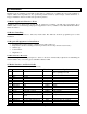
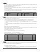
18 Delay Mute Output Open collector, no pull up
19 Delay SCLK Output Open collector, no pull up
20 Delay Data Output Open collector, no pull up
21 Ground
22 Ground
23 Alert relay, normally open Output Relay contacts
24 Alert relay, normally closed Output Relay contacts
25 Speaker mute, common Output Relay contacts
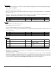
4.6 Parallel/Printer Interface
Pin Function Direction Signal
1 Strobe Output TTL open collector with 27 ohm series resistor and 10k pullup
2 D0 Output TTL with 27 ohm series resistor
3 D1 Output TTL with 27 ohm series resistor
4 D2 Output TTL with 27 ohm series resistor
5 D3 Output TTL with 27 ohm series resistor
6 D4 Output TTL with 27 ohm series resistor
7 D5 Output TTL with 27 ohm series resistor
8 D6 Output TTL with 27 ohm series resistor
9 D7 Output TTL with 27 ohm series resistor
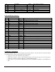
10 Acknowledge Input TTL
11 Busy Input TTL
12
13 Selected Input TTL
14
15 Error Input TTL
16 Init Output TTL open collector with 10k pullup
17 Selected in Output TTL open collector with 10k pullup
18 Ground
19 Ground
20 Ground
21 Ground
22 Ground
23 Ground
24 Ground
25 Ground
4.7 ARi-195e Adjustments
After programming the ARi-195e and connecting the radio interface harness to the radio transceiver, attach the terminal
to the interface harness. Observe normal static prevention practices.
• Apply power to the radio and turn the power switch on.
• Set the service monitor to receive on the transmitter frequency. If the service monitor does not incorporate an
oscilloscope, connect an external oscilloscope to the demodulation output.
• Using a service monitor generate a 1000 Hz signal deviated at 4.0 KHz and adjust R8 to obtain 100mvp-p at
TP1.