
Owner's Manual

May 1995
Supersedes sheet dated 1/95
5/95
10M
CPY-IG
Printed in U.S.A.
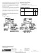
Wiring Diagram
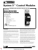
Module, Model RM-30U (30RU). This module shall be system
interconnected by a ten pin plug and harness assembly and
shall be operable with the main control panel.
Upon receipt of the two high going input activation signals,
the solid state circuitry shall apply power for the (solenoid
valve(s) or 24 Vdc relay).
A circuitry disconnect switch shall be provided to deactivate
the circuit during servicing of the system and shall indicate a
trouble condition when the switch is in the off position.
The module shall contain a yellow LED indicator to indicate
an open release circuit when the system is in an otherwise
normal condition. The LED shall be lamp tested from the
control panel.
The model RM-30U (30RU) shall be placement supervised
and shall be Underwriters Laboratories listed and Factory
Mutual approved.
Electrical Information
Module current requirement:
Normal supervisory - 5 mA
Released energized - 1.5A maximum
Maximum line resistance - 3 ohms for typical approved load.
Ordering Information
NOTICE: The use of other than Cerberus Pyrotonics detectors and bases
with Cerberus Pyrotronics control equipment will be considered a
misapplication of Cerberus Pyrotronics equipment and as such void all
warranties either expressed or implied with regards to loss, damage,
liabilities and/or service problems.
Cerberus Pyrotronics
8 Ridgedale Avenue
Cedar Knolls, NJ 07927
Tel: (201) 267-1300
FAX: (201) 397-7008
Model No. Description Ship Wt.
lbs. kg.
RM-30U Releasing Device Module 1 0.45
RM-30RU Releasing Device Module with
Resistors
1 0.45
Cerberus Pyrotronics
50 East Pearce Street
Richmond Hill, Ontario
L4B, 1B7 CN
Tel: (905) 764-8384
FAX: (905) 731-9182
firealarmresources.com