
Owner's Manual
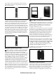

many MXL series systems. The NCC-G maintains an
extensive history log of all system events and has exten-
sive report generation capabilities. User programmable
function buttons are programmable to allow site specific
control function configuration. Multiple NCC-Gs may be
connected to a LifeLINK network. PC ordered separately.
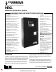
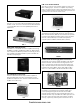
FireFinder NCC-G
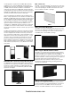
NIM-1R Network Interface Module
The NIM-1R is a full sized slot MXL module that allows the
interconnection or networking of up to 63 MXL systems.
The NIM-1R provides an RS-485 communication path in
either Style 4 or Style 7 wiring configurations. The NIM-1R
allows MXLs to have interpanel logic and communicate in
a peer to peer fashion. The NIM-1R can be programmed
via CSGM logic as an FSI (Foreign System Interface) to
communicate with external building control and annuncia-
tion systems.
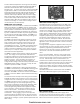
NIM-1R
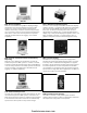
CCU/M Alphanumeric Pager Interface
The CCU/M is a ancillary module that connects to the PIM-
1 to transmit MXL status information in text message
format to an alphanumeric pocket pager. The CCU/M can
be connected to an existing phone line and can dial out to
a pager using its onboard modem to transmit information
via a paging service. The CCU/M can also connect directly
to an existing on-site paging system. Through program-
ming the CCU/M can send different types of events to
different pagers. Up to 8 different messages can be sent
to pagers directly from the CCU/M. Alarms, Troubles,
Supervisory, Security, Arm/Disarm, Status Points, Audible
Status, and Reset can be directed to all or only certain
alphanumeric pocket pagers.
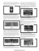
CCU/M
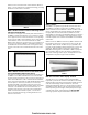
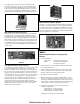
REP-1 Network Repeater Module
The REP-1 is a 1/2 slot MXL network module that provides
the ability to configure the MXL’s local or global networks
in a star or daisy chain configuration. The REP-1 provides
two Style 4 or one Style 7 RS-485 network circuits. Through
the use of the REP-1, the MXL’s local network (MXL-MXLR)
can be expanded up to 64 nodes.
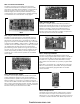
REP-1
MMB-2
Electrical Specifications for Analog Loop
Devices
1. Electrical Ratings:
Supervisory: 24VDC peak, 30mA max.
Alarm: 24 VDC peak, 30mA max.
(60 devices in alarm)
2. All wiring must be in accordance with Article 760 of NEC
or local building codes.
3. Only Cerberus Pyrotronics devices may be used. (See
Table 1) A maximum of 60 devices in any combination
may be connected to a single analog loop.
4. No end of line device required.
5. Both circuits are power limited to NFPA 70/NEC. Each
detector or group of detectors, requires a two wire circuit
of minimum 18 AWG thermoplastic fixture wire enclosed
in a conduit or minimum 18 AWG limited energy shielded
cable without conduit, if permitted by local codes.
6. Total circuit resistance must not exceed 100 ohms.
Maximum capacitance:
0.4µF between + loop and - loop
0.8µF between + loop and chassis
0.8µF between - loop and chassis
7. T-tapping is not allowed on Class A loops
firealarmresources.com