
Owner's Manual
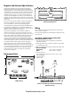
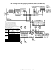

MXL Releasing Service Wiring Diagram (per NFPA 12A, NFPA 13, and NFPA 2001)
Notes:
1. Use only listed solenoids from Table 1.
2. Solenoids supervised for opens only.
3. Polarity shown in supervisory condition.
4. Releasing circuits are not power limited.
5. No end of line device used.
6. Configure CSM-4 circuits as Municipal Tie.
7. Maximum of 5 Pre-Action/Deluge zones per MOM-4.
8. Each MOM-4 must be powered from a separate
ALARM-SAF power supply.
9. Set all position of S2 on the CSM-4 ro OFF (OPEN).
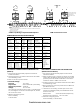
Table 1
Application Make Model Maximum #
per MOM-4
NFPA 13
(Preaction
Deluge)
Skinner LV2LBX25, 24V 5
ASCO TB210A107, 24V 5
ASCO R8210A107, 24V 5
ASCO 8210A107, 24V 5
NFPA 12A
(Halon)
CPY 500-982631, 24V 8
CPY 500-286652, 24V 8
CPY 500-083377, 24V 8
CPY 500-086929, 24V 8
NFPA 2001
(FM-200)
CPY 500-486500 8
firealarmresources.com