
Owner's Manual
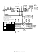


CSM-4 Loop Wiring of Supervised Municipal Tie
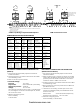
COMPATIBLE NOTIFICATION APPLIANCES
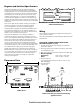
CSM-4 Leased Line Circuit
ELECTRICAL CONNECTIONS FOR LEASED LINE
(NFPA 72 Remote Station)
1. Set switches S3 and S4 and jumpers G1 and G2 as
indicated in Table 2.
2. When a CSM-4 circuit is used as a Leased Line trouble
output, SW1 and SW2 on switch S2 must be set. These
positions permit the default trouble bus to activate the
trouble line. Refer to TABLE 3 to set them.
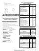
3. All wiring must be in accordance with Article 760 of NEC
or local builsing codes.
4. Both Leased Line circuits are power limited to NFPA 70
per NEC Article 760.
5. Leased Line circuit rating: 24 VDC open circuit Load
must be a compatible polarity reversal labeled remote
station receiver unit.
Rated current: 3mA to 9mA, alarm/supervisory
External circuit resistance: 2K to 5K ohms
6. Minimum emergency power:
60 hour standby / 5 minute alarm
ELECTRICAL CONNECTIONS FOR MUNICIPAL TIE
(NFPA 72)
1. Set switches S3 and S4 and jumpers G1 and G2 as
indicated in Table 2.
2. All wiring must be in accordance with Article 760 of NEC
or local building codes.
3. Both circuits are not power limited.
4. Electrical Ratings:
Trip Coil: 14.5 ohms
Trip Current: 220 to 320mA DC (momentary)
Supervisory Current: 12mA DC
Voltage: 18 to 31 VDC
The total loop resistance from the LLM-1 to the Municipal
Tie, including the 14.5 ohms in the Municipal Tie, should
not exceed 22.5 ohms.
5. Minimum emergency power:
60 hour standby
5 minute alarm
Polarity shown in Normal State
Leased Line Circuits are Power
Limited per NEC 760
External Resistance 2K-5K
OHMS
NOTES:
1. Polarity shown in supervisory state.
2. The total loop resistance from the LLM-1 to the Municipal Tie, including the 14.5 OHMS in the Municipal Tie,
should not exceed 22.5 OHMS.
3. Either circuit may be used.
4. Municipal Tie circuits are not power limited.
Chime/
Strobes
Vibrating
Bells
Electro-Mech.
Horn/Strobes
Electronic Horns
1-Tone with Strobe
Single Stroke Bells
EC-S15-C/F/S
EC-S17-C/F/S
EC-S75-F/S
EC-S110-F/S
BE-F/LC
BF-F/LC
BS-F/LC
BT-F/LC
HN-S15-C/F/S
HN-S17-C/F/S
HN-S75-F/S
HN-S110-F/S
HNH-S15-C/F/S
HNH-S17-C/F/S
HNH-S75-F/S
HNH-S110-F/S
EH-S15-C/F/S
EH-S17-C/F/S
EH-S75-F/S
EH-S110-F/S
BE-SS
BF-SS
BS-SS
BT-SS
Strobes Electronic
S.W./Strobes
Horns/
Horn Strobes
3-Tone
Horns/
Horn Strobes
3-Tone
Sync. Strobes Bell/Strobe Plate
S15-F/FS/FT/S/ST
S17-F/FS/FT/S/ST
S75-F/FS/FT/S/ST
S110-F/FS/FT/S/ST
EW-S15-C/F/S
EW-S17-C/F/S
EW-S75-F/S
EW-S110-F/S
MC-C/F/S
MC-S15-C/F/S
MC-S17-C/F/S
MC-S75-F/S
MC-S110-F/S
MTL-C/F/S
MTL-S15-C/F/S
MTL-S17-C/F/S
MTL-S75-F/S
MTL-S110-F/S
S15S-F/FS/FT/S/ST
S17S-F/FS/FT/S/ST
S75S-F/FS/FT/S/ST
S15-6060H/6090V
S17-6060H/6090V
S75-6090V
S110-6090V
Sync. Electro-Mech.
Horn/Strobes
Sync. Horns/
Horn Strobes
3-Tone
Sync. Horns/
Horn Strobes
8-Tone
Synchronizing
Control Module
Sync. Bell/Strobe Plate
HN-S15S-C/F/S
HN-S17S-C/F/S
HN-S75S-F/S
HNH-S15S-C/F/S
HNH-S17S-C/F/S
HNH-S75S-F/S
MC-S15S-C/F/S
MC-S17S-C/F/S
MC-S75S-F/S
MTL-S15S-C/F/S
MTL-S17S-C/F/S
MTL-S75S-F/S
SCM-F/FW S15S-6060H/6090V
S17S-6060H/6090V
S75S-6090V
Electronic Horns
1-Tone
Chimes Electronic
Slow Whoop
Electro-Mech.
Horns
Tri-Tone Horns Suffixes
EH-C/F/S EC-C/F/S
CH-F/LC/SS
EW-C/F/S HN-C/EP/F/S
HNH-C/EP/F/S
SEA
TTH
C = Ceiling
EP = Explosion Proof
F = Flush
FT = Flush w/Terminals
G = Gang Mount
H = Horizontal
LC = Low Current
S = Surface
SS = Single Stroke
ST = Surface w/Terminals
U = Universal Mount
V = Vertical
W = White
Mini-Horns Mini-Horns/Strobes
8-Tone
Sync. Mini-Horns/
Strobes 8-Tone
MH-1G/1GW
MH-U/UW
MH-S15-U/UW
MH-S17-U/UW
MH-S75-U/UW
MH-S110-U/UW
MHT-1G/1GW
MHT-U/UW
MHT-S15-U/UW
MHT-S17-U/UW
MHT-S75-U/UW
MHT-S110-U/UW
MHST-1G/1GW
MHST-U/UW
MHST-S15S-U/UW
MHST-S17S-U/UW
MHST-S75S-U/UW
MMT-1G/1GW
MMT-U/UW
MMT-S15-U/UW
MMT-S17-U/UW
MMT-S75-U/UW
MMT-S110-U/UW
MMT-S15S-U/UW
MMT-S17S-U/UW
MMT-S75S-U/UW
The SCM-F/FW Synchronizing Control Module must be used with these modules to synchronize the strobes.
firealarmresources.com