
Owner's Manual
pling point. The pipe system shall be supported as required
by local codes. The air sampling system shall be engi-
neered for a maximum transport time of 120 seconds and
have equal sensitivity throughout the entire system.
Before approval to proceed, install or invoice this contract,
an engineering report must be submitted with the following
design information:
l Flow rate through detector in cfm
l Maximum calculated air transport time from the
most distant hole
l Pipe diameter of each segment
l Sample hole diameters and location
l Calculated suction pressure and location of
each sampling hole
l External air flow allowance in feet per second
l Isometric drawing describing the protected area with
pipe segments number, air sampling holes number,
and length of all pipe segments and distances
between holes.
Upon completion of installation, the above-mentioned de-
sign information shall be verified and empirical values re-
corded for periodic maintenance to the system. Suction
pressure shall be measured with a magnehelic manometer
and air velocities with an anemometer.
The AnaLASER
TM
Display Control Panel shall be modular in
construction and consist of one or more Ana-LASER
TM
Display Control Cards.
The AnaLASER
TM
display control card shall monitor one
AnaLASER
TM
detection zone and indicate as a minimum the
following information.
l Smoke intensity in 10% increments by means of an
illuminating-type bar graph display.
l Three programmable alarm set points with red
indicators labeled: Alarm, Pre-Alarm 2, Pre-Alarm 1.
Each alarm level shall have a programmable 0 to 60 second
delay and a form C contact output.
The following system conditions shall be annunciated and
shall have a common form C contact output:
System Operation Normal: steady green light
Power Supply Trouble: flashing yellow
Detector Fail: flashing yellow light
Air Flow Fail: flashing yellow light
CPU Trouble: flashing yellow light
The AnaLASER
TM
Control Card shall store a history of smoke
levels and events. This information shall be accessible
through a computer terminal. Obscuration level storage
rates shall be programmable from 2 seconds to 60 seconds.
The storage capacity shall be at least 40,000 samples, and
downloading shall be possible at increments of 1 to 40,000
from the most recent data stored.
Each display control card unit shall have a 0 to 5 volt analog
output for connection to a strip chart recorder.
The power supply shall provide 24 VDC power, sufficient to
power the entire system and to charge and maintain a
sealed lead acid battery backup supply for 24 hours.
AnaLASER
TM
Detector Specifications
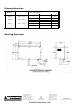
Weight: 16 lb.
Finish: Black matte
Mounting: 1/4 inch bolts, Qty. 4
Input Voltage: 24 VDC +10%
Electrical Connection:
5
/
8
inch flexible conduit
AnaLASER
TM
Detector
Assembly Current: 429mA
AnaLASER
TM
Detector
Current: 300mA
Ambient Environment: 32° to 125° F
Relative Humidity: 0-95%, non-condensing
Sensitivity:
ASD-3 .003 to .03%
obscuration per foot
ASD-6 .006 to .06%
obscuration per foot
ASD-12 .012 to .12%
obscuration per foot
firealarmresources.com