
Owner's Manual

The AnaLASER
TM
air sampling network may be placed in
locations with airflow velocity as high as 20 feet/second. The
area protected by a single detector may be as large as
20,000 square feet, each sampling hole may protect up to
900 square feet. Location and coverage of each sampling
hole is governed by NFPA 72 requirements for spot type
smoke detectors.
The “SNIFF” computerized design program allows the in-
staller to distribute the piping throughout the hazard with
minimal constraints. The program balances the sampling
network by sizing the holes and pipe diameters to insure
equal air intake from each hole with minimum air transport
time to the detector. Consult an authorized Cerberus Py-
rotronics Sales Outlet for assistance with the proper appli-
cation of the AnaLASER
TM
detection system.
The AnaLASER
TM
Detector Assembly
The AnaLASER
TM
detector assembly consists of a fan box
with an AnaLASER
TM
detector. The fan box is an airtight en-
closure which houses a high efficiency, 24 volt DC centrifu-
gal fan. Centrifugal fans are superior to axial fans and
produce the greater suction pressure necessary in an air
sampling system. The fan draws air from the air sampling
network through the AnaLASER
TM
detector. The air passes
without filtration straight through the detection chamber.
The detector’s patented optical system focuses a 100 mi-
cron diameter laser beam across the detector chamber,
and a single photon detection device collects scattered
light from the individual particles of smoke as they traverse
the laser beam.
Smoke concentration is determined by counting these dis-
crete events over a period of time. These individual par-
ticles produce an analog signal which is transmitted to the
control panel.
A large particle size discriminator prevents random large
particles, present in unfiltered air, from generating an alarm
condition. Dust particles which manage to defeat the large
particle rejection circuitry only count as a single particle,
despite their size, and contribute little to the detector’s sig-
nal level. Airflow is monitored with a bead type thermistor
which is cooled by the air passing through the detection
chamber and compared to a reference thermistor mounted
outside the chamber. Should the airflow vary or stop, a com-
parator circuit transmits a signal to the control panel.
The intensity of the laser is monitored and controlled with a
closed-loop control circuit that maintains the stability and
accuracy of the AnaLASER
TM
detector over its life. Compen-
sation is provided by changes in laser intensity due to tem-
perature, aging of components, or contaminant buildup.
This circuit also monitors or supervises the operation of criti-
cal components in the system: laser, photo diode, and opti-
cal assembly. Failure or out of tolerance will result in a
detector fail signal being transmitted to the control panel.
Three detectors with different sensitivity dynamic ranges
are available. Sensitivity selection depends on the minimum
level of smoke to be detected plus the ambient level of air
pollution. It is necessary to conduct an on-site test to deter-
mine which sensitivity range is appropriate for the protec-
tion of given hazard. This test should be conducted before
the installation is commissioned.
The AnaLASER
TM
Control Unit and Power
Supply
Please see Catalog Number 1161.
Eng ineerEng ineer a nd Arc ha nd Arc hiitec ttec t
Sp ecSp ec iiffic a tionsic a tions
The Air Sampling Smoke Detection System shall be
Cerberus Pyrotronics AnaLASER
TM
. The detector shall be
housed in an airtight enclosure with straight- through airflow
design. The air shall pass through the detector without ob-
struction or filter which requires maintenance and which
may inhibit the system’s ability to detect smoke. An optional
exhaust to a
3
/
4
inch pipe, shall be available to return the
sample air back to the area or duct being protected.
The detector shall use a laser as the light source for detect-
ing particles of combustion. The laser light source life ex-
pectancy shall be a minimum of 10 years or greater and the
output energy shall remain constant over that period.
The detector output shall be controlled with a closed- loop
control circuit to maintain the accuracy of the detector. The
light source, the photo diode, and all critical components
shall be supervised within the detector. Upon failure or sig-
nificant variation, detector failure shall be transmitted to the
Ana-LASER
TM
Control Panel. The detector shall also super-
vise the fan and upon failure or significant variation in air-
flow, the detector shall transmit a fault condition signal to
the AnaLASER
TM
Control Panel.
The fan shall be a high-efficiency, ball bearing, electric
commuted centrifugal-type design for long life and shall
create a minimum static pressure of greater than 0.05
inches of water at all sampling points.
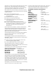
The air sampling piping network shall be a closed-end sys-
tem, constructed of 1 inch,
3
/
4
inch and
1
/
2
inch pipe. The
pipe ends shall be capped within 6 inches of the last sam-
firealarmresources.com