
Instruction Manual

Engineer and Arc hitec t Spec ific a tionsEng ineer and Arc hitec t Spec ific a tions
AA-30U
For Style “Z” systems, a notification appliance circuit for operating 24 Vdc polarized audible alarm devices shall be provided
by a Cerberus Pyrotronics Audible Alarm Class “A” Module, Model AA-30U. This module shall be system inter-connected by
a ten-pin plug and harness assembly and shall be operable with the main control panel.
Upon receipt of a high-going DC actuating signal, the solid state circuitry shall supply operating power for vibrating 24 Vdc
bells, 24 Vdc horns or strobes. The maximum output current shall be limited to 1.5 amperes. The audible devices shall
require a four wire fused, supervised circuit.
The module shall contain a yellow LED indicator lamp to indicate an open or shorted alarm line when the system is in the
normal condition. The LED shall be lamp tested from the main control panel.
The Model AA-30U shall be placement supervised and shall be Underwriters Laboratories, Inc. listed.
End of Line Device,
5.6K, ½W
3 Ohms max
Total Line Resistance
of Notification
Appliance Circuit
Connecting Wires
Polarized Notification
Appliance (See Note 3)
Input Power
(See Note 1)
Actuation
Input
CP-35
CP-35
(See Note 2)
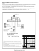
Style Z (Class A) Connected Polarized
Notification Appliances
Polarity Shown in Supervisory Condition:
SUPV 24VDC, 5mA
Alarm 24VDC or 120VAC, 1.5 Max
Notes:
1. When Style Z (Class A) type notification appliance circuit configuration is used, 24 VDC
notification appliances are required. Use EOL device Model EL-31 and DC program plug Model
JP-D in P2
2. Notification appliance circuits may be activated from the silenceable system alarm output
signal, terminal 36 of CP-35, or from the non-silenceable system alarm output signal, terminal 42
of CP-35. When other alarm signals such as coding or time delay/limit are required, see individual
module connection diagrams.
3. Refer to the BI-35 Installation Instructions, P/N 315-086257, for detailed wiring information
when using the AA-30U in conjunction with the BI-35 module.
4. Use only the compatible polarized notification appliances in the following table.
5. To use power limited wiring to NFPA 70, NEC Article 760, the notification appliance circuits
(terminals 3, 4, 7, and 8) must use the PLM-35 module. Refer to Instructions P/N 315-093495
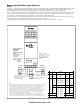
TABLE 1
COMPATIBLE NOTIFICATION APPLIANCES
Strobes
Electronic
Horns
1-Tone
with strobe
Electro-Mech.
Horn/Strobes
Electronic
S.W./Chime
Chimes/
Strobes
S15-FS
S15-F
S15-FT
S15-ST
S15-S
S17-FS
S17-F
S17-S
S17-FT
S17-ST
S75-FS
S75-F
S75-S
S75-FT
S75-ST
S110-FS
S110-F
S110-S
S110-FT
S110-ST
EH-S15-F
EH-S15-S
EH-S15-C
EH-S17-F
EH-S17-S
EH-S17-C
EH-S75-F
EH-S75-S
EH-S110-F
EH-S110-S
HN-S15-F
HN-S15-S
HN-S15-C
HNH-S15-F
HNH-S15-S
HNH-S15-C
HN-S17-F
HN-S17-S
HN-S17-C
HNH-S17-F
HNH-S17-S
HNH-S17-C
HN-S75-F
HN-S75-S
HNH-S75-F
HNH-S75-S
HN-S110-F
HN-S110-S
HNH-S110-F
HNH-S110-S
EW-S15-F
EW-S15-S
EW-S15-C
EW-S17-F
EW-S17-S
EW-S17-C
EW-S75-F
EW-S75-S
EW-S110-F
EW-S110-S
EC-S15-F
EC-S15-S
EC-S15-C
EC-S17-F
EC-S17-S
EC-S17-C
EC-S75-F
EC-S75-S
EC-S110-F
EC-S110-S
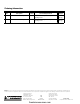
Vibrating
Bells
Horns/Horn Strobes
3-Tone 8-Tone
Electro-
Mech. Horns
Electronic
Horns
1-Tone
BT-F
BE-F
BS-F
BF-F
BT-LC
BE-LC
BS-LC
BF-LC
MC-F
MC-S
MC-C
MC-S15-F
MC-S15-S
MC-S15-C
MC-S17-F
MC-S17-S
MC-S17-C
MC-S75-F
MC-S75-S
MC-S110-F
MC-S110-S
MT-F
MT-S
MT-C
MT-S15-F
MT-S15-S
MT-S15-C
MT-S17-F
MT-S17-S
MT-S17-C
MT-S75-F
MT-S75-S
MT-S110-F
MT-S110-S
HN-F
HN-S
HN-C
HNH-F
HNH-S
HNH-C
HNH-EP
HN-EP
EH-F
EH-S
EH-C
Tri-Horn
TTH
Chimes Electronic Slow Whoop
EC-F
EC-S
EC-C
CH-F
EW-F
EW-S
EW-C
firealarmresources.com