
Instruction Manual

The RemCon module shall have a key switch that enables
or disables the module. It also shall have LEDs for Power,
Alarm, Trouble, Supervisory condition, Bypass or Bell
Silence condition, Service Required, and Polling.
The module’s “Polling” LED shall blink periodically to show
the IXL system supervision, that is, polling of the module.
The RemCon shall also have LEDs and corresponding
function keys for: Acknowledge, Reset, Drill.
The RemCon shall be equipped with a sounder horn. If
desired, the sounder horn can be disabled.
Programming
Software Configuration
To use a RemCon module on a system, it is necessary to
program and enable the module in the IXL computer
laptop configuration software. (For details, reference the
IXL Programming Manual.)
Module Address Programming
Program the RemCon module’s address by entering the
PROGRAM mode from the IXL panel and applying the
magnet to the appropriate place on the module’s front
cover.
Technical Data
Electrical Characteristics
Normal 8mA
Alarm 11mA
The RemCon’s Acknowledge, Reset and Drill function keys
become operational only when the operator inserts and
turns the RemCon’s key switch using the control panel key.
Mounting
Install the RemCon in a 4
11
/
16
" x 4
11
/
16
" x 2
1
/
8
" backbox. Con-
nect the system wiring to the screw terminals on the
RemCon module.
Terminal Connections
Terminal Function
24V Provides power
DATA Serial network communication
line-V Return line
ER Drain wire
+AP/-AP Auxiliary power connections
(optional)
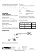
Mount the RemCon module to a 4 11/16 inch by 2 1/8 inch
deep electrical backbox. If an auxiliary power supply is
used, be sure J2 is in position “A.” To disable the sounder
horn, move and open the safety pin jumper SW5.
Observe wiring polarity when making connections. Dam-
age may result from incorrect wiring.
Ordering Information
March 1994
Supersedes sheet dated 8/93
Cerberus Pyrotronics
50 East Pearce Street
Richmond Hill, Ontario
L4B, 1B7 CN
Tel: (905) 764-8384
FAX: (905) 731-9182
4/96
5M
CPY-IG
Printed in U.S.A.
Cerberus Pyrotronics
8 Ridgedale Ave.
Cedar Knolls, NJ 07927
Tel: (201) 267-1300
FAX: (201) 397-7008
Wiring Diagram
NOTICE: The use of other than Cerberus Pyrotronics detectors and bases with Cerberus
Pyrotronics control equipment will be considered a misapplication of Cerberus Pyrotronics
equipment and as such void all warranties either expressed or implied with regards to loss,
damage, liabilities and/or service problems.
Model No. Description Part No.
RemCon
IXL Remote Control
Module
500-692183
FR5B
RemCon Semi-flush Trim
Ring (Black)
500-692607
firealarmresources.com