
User's Manual Part 9


5 7
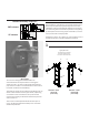
Tightly attach the support bands (12)
to the tower pipe in the antenna
mounting position. The antenna mount
channel will rest on these bands.
6
23
12
24
14
15
Tower pipe
Hoist
line
Hoist
line
Hoist line
choker
Angle
adaptor
27
27
24
14
15
10
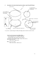
Antenna center
offset left
Antenna center
offset right
Very loosely attach the strut (29) to the mount
angle (27) with the front strut angle (5). Very loosely
attach the other end of the strut to a tower member
with the rear strut angle (6); attach this end so
that the strut is as parallel as possible to the
antenna axis for maximum stability. The deviation
angle from this parallel position should be no
more than 25° in any direction.
Leave all strut attaching hardware loose until after
elevation and azimuth adjustments are done.
Then, tighten the hardware according to Table 2.
25°
29
27
*Bolt requires a 13.5
mm (0.531") mounting
hole in tower member.
Consult with the tower
manufacturer
regarding advisability
of drilling into a tower
member, or for a
recommendation of a
special mounting
method.
15
14
5
27
17
16
18
22
29
22*
7
16
17
11
6
24
14
15
Install the feed according to Bulletin 237285 (feed
not shown for clarity). Attach hoist lines to the upper
mount angle (27) as shown: add a hoist line choker
through the angle adaptor of a shielded antenna.
Raise the antenna to the tower pipe and position
it on the support bands as close to its
operating position as possible. Tightly attach the
mount to the tower pipe with two U-bolts (10).