
User's Manual Part 9


2
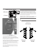
Loosely attach the base plate (26) to the
channel (28). Note: the channel
depth varies according to the origin of
manufacture, which determines whether
or not to use the spacer plate (8).
26
28
8
23
14
15
1
Spacer plate:
add or discard
according to
channel depth
measurement
(see below)
Antenna center
offset right
Antenna center
offset left
3
Very loosely attach both angles (27) to the
base plate (26). Loosen the jam nuts and set
both turnbuckles (9) with their eye centers
at the mid-travel position. Loosely
attach the turnbuckles as shown.
Antenna center
offset left
21
2
9
2
27
27
15
14
Set turnbuckle
eye centers
13.5 to 14" (344 to
356 mm) apart
22
14
15
20
2
9
3
14
15
26
4
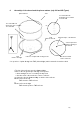
Position the angles (27) of the mount on the
antenna mounting ring parallel to the antenna
top. The antenna top is indicated by red tape on
the reflector rim. Carefully align the mounting
holes and loosely add the attaching hardware.
Important: Partially tighten each bolt while checking to be
sure that the remaining untightened bolts are not
binding in the holes. If binding occurs, loosen
all partially tightened bolts. Then, slightly reposition the
mount to the reflector and repeat the procedure. If the
mount is improperly positioned on the reflector when
the bolts are tightened, distortion of the reflector
can occur. After the four bolts are partially tightened,
fully tighten them as given in Table 2.
Partially tighten the bolts holding the angles to the
base plate enough to compress the lock washers.
Red tape at
reflector top
Antenna
mounting
ring
Base
plate
Antenna
mounting
ring
27
2719
4
25
27
25
16
17
Antenna center
offset right
Antenna center
offset left
Spacer plate
added
Spacer plate
discarded
23
28
2"
(51 mm)
Tower
pipe
1.7"
(44 mm)
28
23
8
Antenna center
offset right