
User's Manual Part 9


1
2
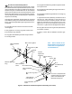
Rear surface of
antenna reflector
2
Insert guy wire here
and bring back through
feed mounting hole
Antenna Assembly Sequence
Antenna
Feed
mounting
hole
VHP antenna
2
1
3
Description
Notice
The installation, maintenance, or removal of antenna sys-
tems requires qualified, experienced peronnel. This
installation instructions have been written for such person-
nel. Antenna systems should be inspected once a year by
qualified personnel to verify proper installation, mainte-
nance, and condition of equipment.
results of improper or unsafe installation practices.
Table 1. Feed Parts List
Item Description Qty
1 Feed Assembly 1
2 Guy Wire 3
3 M6x16lg SHCS, ss. 4*
4 M6 Lockwasher, ss. 4*
5 O-Ring 1*
6 Silicone Grease, tube 1*
7 Conductive grease, tube 2*
ss - Stainless Steel
* - Part of feed kit
Table 2. Fastener Torque Specifications
Fastener Torque value in N·m (lb·ft ) for each fastener size
Size M5 M6 M8 M10 M12 M16
Stainless 4.5 7.7 18.7 39.2 65.1 161
steel (3.3) (5.7)(13.8)(28.9) (48) (118.7)
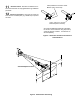
to be mounted into the reflector of the antenna.
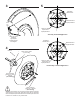
Included with the feed are guy wires. An notch on the feed
hub indicates the direction of polarization and the feed can
be rotated to adjust polarization.
This feed is designed to interface with a CERAGON RFU and
Ceragon disclaims any liability or responsibility for the