
User's Manual Part 9

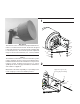

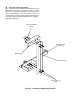

Attachment of Antenna Support Clamp
(Refer to Figures 2 & 6). Determine desired height
for antenna and attach antenna band clamps to mounting
pipe at required location using M12 x 40mm long bolts,
lockwashers & nuts. Fully tighten hardware.
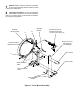
Attachment of the Antenna to the Mounting Pipe
(Refer to Figures 2 & 7). Rest the lower end of the
main channel on the antenna support clamp. Attach an-
tenna to mounting pipe using M20 'U'-bolt, M12 'U'-bolt and
their respective lockwashers & nuts. Tighten the nuts on
the 'U'-bolts until the lockwashers begin to close. Roughly
align the antenna onto its operating path.
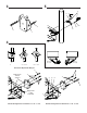
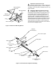
Figure 7. Attachment of Azimuth Adjustment Strut (6ft version)
7
6
M20 Lockwasher &
Nut
Reflector
Mounting Ring
'U'-Bracket
M20 x 45mm lg Bolt
M20 x 90 lg Bolt,
Lockwasher & Nut
M16 x 55 lg Coach
Bolt & Flatwasher
Setscrew
& Locknut
Azimuth Adjustment
Nut
Angle Bracket
Note : Holes should not be
drilled without prior approval
of the tower or support struc-
ture manufacturer.
M12 x 40mm lg Bolt,
Lockwasher & Nut
Band
Clamp
Ø115mm
Mounting
Pipe
Band
Clamp
-'
#
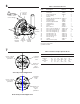
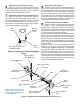
Determine Strut Orientation.
Suitable mounting points must be provided on the
tower or main support structure prior to installation of the
azimuth adjustment strut and the fixed strut (if required).
For structural efficiency, the struts should be installed par-
allel to the antenna axis (ie in the direction of final trans-
mission path). When it is not possible to mount the struts in
this manner due to tower or outrigger considerations, the
struts may be positioned anywhere within an angular 'cone'
relative to the reflector axis as shown in Figure 9.
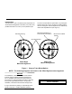
Azimuth Adjustment Strut Installation.
Attach 'U'-bracket to reflector mounting ring at point
'D', as shown in Figure 6, using an M20 x 45mm long bolt,
lockwasher & nut. Attach the pre-drilled end of the azimuth
adjustment strut to the azimuth 'U'-bracket on the reflector
using an M20 x 90mm long bolt, lockwasher & nut as shown
in Figure 6. Do not fully tighten at this stage.
Assemble the azimuth adjustment components and the strut
clamp on to the free end of the strut as shown in Figure 6.
Position the azimuth adjustment nuts such that they are
approximately at the mid-point of the azimuth bolt threads.
Tighten the 'U'-bolt and clamp assembly set screws suffi-
ciently enough to prevent the assembly from falling off the
strut at this stage.
Rotate the antenna in azimuth until pointing (as closely as
possible) in the direction of the final transmission path.
Loosen the azimuth adjustment assembly 'U'-bolt and clamp
set screws and slide the assembly until the clamp can be
installed on a suitable tower member. Fully tighten the 'U'-
bolt nuts to secure the angle bracket to the strut. Ensure
that the tab of the azimuth bolt is secured against the strut
clamp using the locknut provided. Take up excessive slack
in the remaining hardware at this stage in order to perform
final azimuth and elevation adjustments.
8
Tower
Member
Ø18mm Hole for
M16 Bolt
9
Side Strut
Clamp Assembly
M16 Lockwasher
& Nut
Side Strut
'U'-Bolt