
Instructions


12
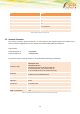
Pin
Signal
1
VUSB
2
D -
3
D +
4
not connected
5
GND
Table 4: Mini USB Pin description
2.3 Antenna Connector
The antenna connector allows transmission of radio frequency (RF) signals between the modem and an
external customer-supplied antenna. The modem is fitted with a 50Ω, FME male coaxial jack.
Output Power:
2 Watt Peak (Class 4) GSM900/850
1 Watt Peak (Class 1) GSM1800/1900
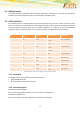
The antenna that the customer chooses to use should fulfil the following requirements:
Frequency range
Quad Band
GSM 850/900 MHz
GSM 1800/1900 MHz
Depending by frequency band(s) provided by
the network operator, the customer shall use
the most suitable antenna for that/those band(s)
Bandwidth
80 MHz in EGSM 900, 70 MHz if GSM 850,
170 MHz in DCS, 140 MHz PCS band
Gain
> 1.5 dBi
Impedance
50 ohm
Input power
> 2 W peak power
VSWR absolute max.
10:1
VSWR recommended
<= 2:1
Table 5: Recommended characteristics of the serial port signals