
User manual


9
2 Electrical Description
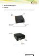
The modem uses the following industry standard connectors:
RJ11 6-way (power/IO connector) – Not connected for USB power variant
Mini USB (for data) – Also the power connector for USB power variant
SIM card reader
FME male coaxial jack (antenna connector)
Sub-D female socket, 9 pin (RS232 serial port)
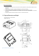
2.1 Power Connector
An RJ11 6-way connector, as shown and described below, serves as a means of supplying and
controlling DC power to the modem.
The supply voltage, VCC, required by the modem is in the range 5V - 32V DC. Application of the supply
voltage does not switch the modem on. To do so an additional active-high control signal, TO_IN, must
be applied for > 5 seconds.
Please see chapter “3.1 Switching the modem on” for further important details about TO_IN and power
supply requirements, especially if TO_IN is applied in parallel to VCC.
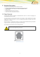
VCC and GND are reverse-polarity and over-voltage protected.
This does not apply for the GND on the antenna connector if this coax GND / shield are
connected to your applications ground-plane.
PIN: 6 5 4 3 2 1
Figure 4: RJ11 Pin Connector