
User manual

14
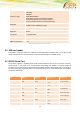
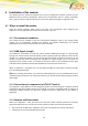
PIN
Signal
Direction
Voltage levels
Description
8
CTS
Output
> + 4V
< - 4 V
Clear to send
9
RI
Output
> + 4V
< - 4 V
Ring indicator
Table 6: Electrical characteristics of the serial port signals
2.5.1 Serial Data
The modem supports the standard data character format of
Programmable baud rate
Auto-configuration mode with auto-baud.
2.5.2 Serial Data Signals
Serial Data From Modem (RD)
RD is an output signal that the modem uses to send data to the application.
Serial Data To Modem (TD)
TD is an input signal, used by the application to send data to the modem.
2.5.3 Control Signals – RTS, CTS, DTR, DSR, DCD, RI
Request to Send (RTS)
RTS is used to condition the DCE for data transmission. The default level is high by internal pull up. The
exact behaviour of RTS is defined by an AT command. Software or Hardware control can be selected.
Hardware flow is the default control. The application must pull RTS low to communicate with the
modem. The modem will respond by asserting CTS low, indicating it is ready for communication.
Clear To Send (CTS)
CTS indicate that the DCE is ready to transmit data. The default level is high. You can define the exact
behaviour of CTS through an AT command, and can select software or hardware flow control.
Data Terminal Ready (DTR)
DTR indicates that the DTE is ready to transmit and receive data. It also acts as hardware ‘hang-up’,
terminating calls when switched high. The signal is active low. You can define the exact behaviour of
DTR with an AT command. The DTR line can also be used to switch on the modem when activated for
0.2 seconds. The DTR line must be deactivated prior to switching off the modem to ensure it switches
off (powers down) correctly.
Data Set Ready (DSR)
An active DSR signal is sent from the modem to the application (DTE) to confirm that a communications
path has been established. DSR has two modes of operation, settable using the AT command AT&S.
Data Carrier Detect (DCD)
DCD indicates that the DCE is receiving a valid carrier (data signal) when low. You can define the exact
behaviour of DCD with an AT command.
Ring Indicator (RI)
RI indicates that a ringing signal is being received by the DCE when low. You can define the exact
behaviour for RI with an AT command.