
User manual

12
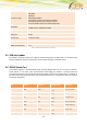
The table below describes the signals on the USB connector.
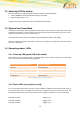
HT910 E Pin Layout for Mini USB connector:
Figure 5: Mini USB Type A/B connector
Pin
Signal
1
VUSB
2
D -
3
D +
4
not connected
5
GND
Table 4: Mini USB Pin Description
2.3 Antenna Connector
The antenna connector allows transmission of radio frequency (RF) signals between the modem and an
external customer-supplied antenna. The modem is fitted with a 50Ω, FME male coaxial jack.
Output Power:
2 Watt Peak (Class 4) GSM900/
1 Watt Peak (Class 1) GSM/1900
The antenna that the customer chooses to use should fulfil the following requirements: