
User manual


10
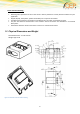
Pin
Description
1
VCC
2
ADC_IN (not applicable in USB Power variant)
3
HR_IN
4
TO_IN
5
optional - DIG_OUT
6
GND
Table 1: Pin Description
PIN
Signal
Direction
Limits
Description
1
VCC
Input
5 – 32V
Positive power input, DC
2
ADC_IN or
not connected
Input
0 – 32V
- Analogue Input
3
HR_IN
Input
5 – 32V
Active high control line used to
switch off
VIH > 5V, VIL < 0.5V
Power off: t > 5s
4
TO_IN
Input
5 – 32V
Positive edge triggered signal; used
to switch on the
modem
VIH > 5V, VIL < 0.5V
Power on: t > 5s
5
DIG_OUT / or not connected
Output
5 – VCC
max. 32V
- optional Digital Output
6
GND
Input
-
Negative power (ground) input and
return
path for TO_IN and HR_IN
Table 2: RJ11 Pin and Signals Description
2.1.1 Analog Input
The following command has to be used to initialise and to read the status of the analogue input:
AT#ADC=1,2,0 or AT#ADC=1,2
Response:
#ADC: <digital value> e.g. #ADC: 119
ADC_ IN ≈ 0,03333V x digital value
ADC_IN [V]
5V
12V
24V
32V
digital value
150
360
720
960
Table 3: Exempels Analog Input