HT910 E Terminal User Manual Revision 1.
Important information This technical description contains important information for start up and use of the HT910 E Terminal. Read it carefully before you start working with the HT910 E Terminal. The warranty will be void should damage occur due to non-compliance with these instructions for use. We cannot accept any responsibility for consequential loss. We cannot be held responsible for material loss or personal injury that is due to incompetent use or non-compliance with the safety instructions.
Before putting a device into operation, it has to be clarified, whether this device or module is meant for the field of application. In case of doubt ask specialists or the manufacturer of the device. Please note that we are not responsible for any errors in usage or connection. Therefore we cannot accept any responsibility for consequential loss. Devices which operate with >32 Volt have to be connected by a specialist.
Table of Contents Important information ...................................................................................................................................................... 2 Safety Instructions ............................................................................................................................................................ 2 1 2 Mechanical Description ...............................................................................................................
4.1.4 4.2 Network and Subscription....................................................................................................................... 19 How to install the modem .............................................................................................................................. 20 4.2.1 Power supply ........................................................................................................................................... 20 4.2.2 Securing the modem .......
Table Overview Table 1: Pin Description .................................................................................................................................................. 10 Table 2: RJ11 Pin and Signals Description ....................................................................................................................... 10 Table 3: Exempels Analog Input ..............................................................................................................................
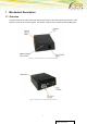
1 Mechanical Description 1.1 Overview The pictures below show the mechanical design of the HT910 E Terminal along with the positions of the different connectors and mounting holes. The HT910 E Terminal case is made of durable PC/ABS plastic.
Please note the following: Mounting holes positioned at two of the corners make it possible to securely bolt the modem into your application. Keypad, display, microphone, speaker and battery are not part of the modem. The SIM card is mounted in the modem, accessible by the user under a lid without any tools. The pins and electrical characteristics or the modem’s various connectors are described in “2. Electrical Description” Information about the antenna connector is found in “2.
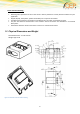
2 Electrical Description The modem uses the following industry standard connectors: RJ11 6-way (power/IO connector) – Not connected for USB power variant Mini USB (for data) – Also the power connector for USB power variant SIM card reader FME male coaxial jack (antenna connector) Sub-D female socket, 9 pin (RS232 serial port) 2.1 Power Connector An RJ11 6-way connector, as shown and described below, serves as a means of supplying and controlling DC power to the modem.
Pin 1 2 3 4 5 6 Description VCC ADC_IN (not applicable in USB Power variant) HR_IN TO_IN optional - DIG_OUT GND Table 1: Pin Description PIN Signal Direction Limits Description 1 VCC Input 5 – 32V Positive power input, DC 2 ADC_IN or not connected Input 0 – 32V - Analogue Input Active high control line used to switch off VIH > 5V, VIL < 0.5V Power off: t > 5s Positive edge triggered signal; used to switch on the modem VIH > 5V, VIL < 0.
2.1.2 Digital Output switched voltage is VIN; high side switch max. Output 400mA short circuit protected ESD protected under full control of embedded application The following command has to be used to initialize and to set the digital output: AT#GPIO=6,1,1 output switched on AT#GPIO=6,0,1 output switched off 2.
The table below describes the signals on the USB connector. HT910 E Pin Layout for Mini USB connector: Figure 5: Mini USB Type A/B connector Pin Signal 1 VUSB 2 D- 3 D+ 4 not connected 5 GND Table 4: Mini USB Pin Description 2.3 Antenna Connector The antenna connector allows transmission of radio frequency (RF) signals between the modem and an external customer-supplied antenna. The modem is fitted with a 50Ω, FME male coaxial jack.
Dual Band GSM /900/ 1900 MHz UMTS 900/2100 MHz Depending by frequency band(s) provided by the network operator, the customer shall use the most suitable antenna for that/those band(s) 80 MHz in EGSM 900, 170 MHz in DCS, 140 MHz PCS band Frequency range Bandwidth Gain > 1.5 dBi Impedance 50 ohm Input power > 2 W peak power VSWR absolute max. 10:1 VSWR recommended <= 2:1 Table 5: Recommended antenna parameters 2.
PIN Signal Direction Voltage levels Description 8 CTS Output > + 4V <-4V Clear to send 9 RI Output > + 4V <-4V Ring indicator Table 6: Electrical characteristics of the serial port signals 2.5.1 Serial Data The modem supports the standard data character format of Programmable baud rate Auto-configuration mode with auto-baud. 2.5.2 Serial Data Signals Serial Data From Modem (RD) RD is an output signal that the modem uses to send data to the application.
3 Operation 3.1 Switching ON the modem There are two ways to switch on the modem, once power is applied. assert TO_IN to high level for > 5s activate the RS232 control line DTR The modem is fully operational after 4 seconds. Logging onto a network may take longer than this and is outside the control of the modem. The modem can be configured to start up at the time power is applied by permanently tying power connector signals TO_IN (pin 4) and VCC (pin 1) together.
3.2 Switching OFF the modem There are two ways to switch off (power down) the modem as described below: use the AT#SHDN command; DTR permanently to low (0,8V) HR_IN to high level for t > 5s A delay of up to 10s is experienced as the modem logs off the network 3.3 Optional Low Power Mode In addition to turning the device completely off the terminal can placed into a low power mode while maintaining connectivity.
Switching off GPIO3 at#gpio=3,0,1 These LEDs can be controlled e.g. by an external microcontroller via at-commands issued to the terminal via the serial RS232 interface. They can be used for signalling any useful status of the external application such as: error indication status of communication (GPRS, SMS, CSD, etc.
CEP AG may refuse warranty claims where evidence of product misuse is found. 3.7 SIM card precautions Before handling the SIM card in your application, ensure that you are not charged with static electricity. Use proper precautions to avoid electrostatic discharges. When the SIM card hatch is opened, the SIM card connectors lie exposed under the SIM card holder. Caution! Do not touch these connectors! If you do, you may release an electrical discharge that could damage the modem or the SIM card.
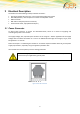
4 Installation of the modem This chapter gives you advice and helpful hints on how to integrate the HT910 E Terminal into your application from a hardware perspective. Please read the information given in “Safety and Product Care”, page 10 and then read the information in this section before starting your integration work. 4.1 Where to install the modem There are several conditions which need to be taken into consideration when designing your application as they might affect the modem and its function.
4.2 How to install the modem 4.2.1 Power supply Use a high-quality power supply cable with low resistance. This ensures that the voltages at the connector pins are within the allowed range, even during the maximum peak current. When the unit is powered from a battery or a high current supply, connect a fast 1.25A fuse in line with the positive supply. This protects the power cabling and modem. 4.2.
4.3.3 Antenna placement The antenna should be placed away from electronic devices or other antennas. The recommended minimum distance between adjacent antennas, operating in a similar radio frequency band, is at least 50cm. If signal strength is weak, it is useful to face a directional antenna at the closest radio base station. This can increase the strength of the signal received by the modem. The modem’s peak output power can reach 2W. RF field strength varies with antenna type and distance.
4.5 CEP Certified Accessories Product Description Power supply 230V AC / 12 VPC 6pin RJ11 connector Power cable 6pin RJ11 connector with open ends Minimag Antenna FME female, 900/1800 MHz Stub Antenna FME female, 900/1800 MHz Rectangular Antenna FME female, Quad-band Roof-mount antenna FME female waterproof, 900/1800 MHz RS232 cable 1.5m for PC connection Table 8: Accessoires List Please contact your distributor or CEP AG for availability or check CEP’s webpage www.cepag.de.
5 Technical Data Product features: Product Features UMTS Power class 3 (24dBm) GSM 900 Power class 4 (33dBm) GSM 1900 Power class 1 (30dBm) GSM 900 Power class E2 (27dBm) GSM 1900 Power class E2 (26dBm) Control via AT commands according to GSM 07.05, 07.07 and proprietary Telit Serial Port Multiplexer GSM 7.10 SIM Access Profile Supply voltage range: 5 – 32 V/DC TCP/IP stack access via AT commands Sensitivity: o -107 dBm (typ.)@ 900 MHz o -106 dBm (typ.
GPRS Class 12 EDGE Class 33 o Max 236.8 kbit/s uplink o Max 296 kbit/s downlink UMTS 384 kbits uplink/downlink HSPA category 6 in uplink and up to category 14 in downlink o Uplink HSUPA 5.76Mbit/s o Downlink Up to 7.
6 Abbreviations Abbreviation Explanations CBM Cell Broadcast Message CBS Cell Broadcast Service CSD Circuit Switched Data DCE Data Circuit Terminating Equipment DTE Data Terminal Equipment DTMF Dual Tone Multi Frequency EFR Enhanced Full Rate EMC Electro-Magnetic Compatibility ETSI European Telecommunication Standards Institute FR Full Rate GPRS General Packet Radio Service GSM Global System for Mobile Communication HR Half Rate HSCSD High Speed Circuit Switched Data ITU-T ME
7 Mark of Conformity The HT910 Terminal will carry the following certificates: 26
8 Service and Support To contact customer support please use the contact details below: Customer Support CEP AG Raiffeisenallee 12b 82041 Oberhaching Germany E-mail: support@cepag.de or Tel. +49-89-450 292 – 11 Information about CEP AG, products and accessories is available on the following web site: http://www.cepag.
9 Documentation Change Log Revision Date Changes Rev 1.0 1.07.2013 Initial Version Rev. 1.2 21.03.2014 Update Document Layout Rev. 1.3 20.01.2015 Addition of Section 4.4.