
User manual

CEP AG Revision 1.3
_________________________________________________________________________________
__________________________________________________________________________________________
Page 7 of 28
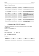
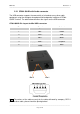
Signals of Power Connector
PIN Signal Direction Limits Description
1 VCC Input 5 – 36V Positive power input, DC
2
ADC_IN or
not connected
Input 0 – 36V
- Analogue Input in GT864 PY
- No connection in GT864 Quad version
3 HR_IN Input 5 – 36V
Active high control line used to switch off
V
IH
> 5V, V
IL
< 0.5V
Power off: 1s < t < 2s
4 TO_IN Input 5 – 36V
Positive edge triggered signal; used to
switch on the
modem
V
IH
> 5V, V
IL
< 0.5V
Power on: t > 1s
5
DIG_OUT / or
not connected
Output
5 – VCC
max. 36V
- Digital Output in GT864 PY
- No connection in GT864 Quad version
6 GND Input -
Negative power (ground) input and return
path for TO_IN and HR_IN
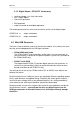
2.1.1 Analogue Input - GT864 PY Variant only
The following command has to be used to initialise and to read the status of the
analogue input:
AT#ADC=1,2,0 or AT#ADC=1,2
Response:
#ADC: <digital value> e.g. #ADC: 119
ADC_ IN ≈ 0,026V x digital value
Examples:
ADC_IN [V] 5V 12V 24V 32V
digital value 192 461 923 1230