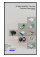
CEP AG Revision 1.3 _________________________________________________________________________________ GT864-QUAD/PY Terminal Technical Description Rev. 1.3 CEP AG Raiffeisenallee 12b 82041 Oberhaching Germany Phone: +49 89 450 292 – 0 Fax: +49 89 450 292 – 22 www.cepag.de Internet: Mail: info@cepag.
CEP AG Revision 1.3 _________________________________________________________________________________ Important information This technical description contains important information for start up and use of the GT864-QUAD/PY Terminal. Read it carefully before you start working with the GT864-QUAD/PY Terminal. The warranty will be void should damage occur due to non-compliance with these instructions for use. We cannot accept any responsibility for consequential loss.
CEP AG Revision 1.3 _________________________________________________________________________________ Contents Important information............................................................................................................................... 2 Safety Instructions ................................................................................................................................... 2 1 Mechanical Description.......................................................................
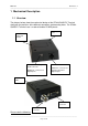
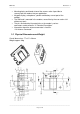
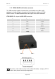
CEP AG Revision 1.3 _________________________________________________________________________________ 1 Mechanical Description 1.1 Overview The pictures below show the mechanical design of the GT864-QUAD/PY Terminal along with the positions of the different connectors and mounting holes. The GT864QUAD/PY Terminal case is made of durable PC/ABS plastic.
CEP AG Revision 1.3 _________________________________________________________________________________ • • • • • Mounting holes positioned at two of the corners make it possible to securely bolt the modem into your application. Keypad, display, microphone, speaker and battery are not part of the modem. The SIM card is mounted in the modem, accessible by the user under a lid without any tools. The pins and electrical characteristics or the modem’s various connectors are described in “2.
CEP AG Revision 1.3 _________________________________________________________________________________ 2 Electrical Description The modem uses the following industry standard connectors: • • • • • RJ11 6-way (power connector) Mini USB (audio- / IO- connector) SIM card reader FME male coaxial jack (antenna connector) Sub-D female socket, 9 pin (RS232 serial port) 2.1 Power Connector An RJ11 6-way connector, as shown and described below, serves as a means of supplying and controlling DC power to the modem.
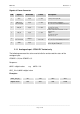
CEP AG Revision 1.3 _________________________________________________________________________________ Signals of Power Connector PIN Signal Direction Limits Description 1 VCC Input 5 – 36V Positive power input, DC 2 ADC_IN or not connected Input 0 – 36V - Analogue Input in GT864 PY - No connection in GT864 Quad version 3 HR_IN Input 5 – 36V 4 TO_IN Input 5 – 36V 5 DIG_OUT / or not connected Output 5 – VCC max.
CEP AG Revision 1.3 _________________________________________________________________________________ 2.1.2 Digital Output - GT864 PY Variant only • • • switched voltage is VIN; high side switch max. Output 400mA short circuit protected • • ESD protected under full control of embedded application The following command has to be used to initialise and to set the digital output: AT#GPIO=3,1,1 output switched on AT#GPIO=3,0,1 output switched off 2.
CEP AG Revision 1.3 _________________________________________________________________________________ 2.2.1 GT864 QUAD with Audio connector The USB connector supports the connectivity of a headset or any other audio equipment using the analogue microphone and loudspeaker interface of GT864QUAD Terminal. The table below describes the signals on the USB connector.
CEP AG Revision 1.3 _________________________________________________________________________________ Voice Features – please read the AT command manual for integration: Telephony, Emergency call Half rate, full rate, enhanced full rate and adaptive multi rate voice codec (HR, FR, EFR, AMR) • Superior Echo cancellation & noise reduction • DTMF • • 2.2.2 GT864 PY with GPIO At the mini USB connector are 4 inputs, with the following technical description: • max. voltage VIN is 30V • low level: 0...
CEP AG Revision 1.3 _________________________________________________________________________________ at#GPIO=7,2,0 (read GPIO7, PIN3 Mini USB) at#GPIO=,8,2,0 (read GPIO8, PIN4 Mini USB) 2.3 Antenna Connector The antenna connector allows transmission of radio frequency (RF) signals between the modem and an external customer-supplied antenna. The modem is fitted with a 50Ω, FME male coaxial jack.
CEP AG Revision 1.3 _________________________________________________________________________________ The electrical characteristics of the serial port signals are shown below: PIN Signal Direction Voltage levels Description 1 DCD Output > + 4V <- 4 V Data carrier detect 2 RD Output > + 4V <- 4 V Received data 3 TD Input > + 2,4V < 0.8 V Transmitted data 4 DTR Input > + 4V < 0.
CEP AG Revision 1.3 _________________________________________________________________________________ Clear To Send (CTS) CTS indicate that the DCE is ready to transmit data. The default level is high. You can define the exact behaviour of CTS through an AT command, and can select software or hardware flow control. Data Terminal Ready (DTR) DTR indicates that the DTE is ready to transmit and receive data. It also acts as hardware ‘hang-up’, terminating calls when switched high. The signal is active low.
CEP AG Revision 1.3 _________________________________________________________________________________ many milliseconds) or very small transitions (e.g. only few volts instead of 0V to VCC) will not turn on the module (since they are not considered to be a “positive edge”).
CEP AG Revision 1.3 _________________________________________________________________________________ 3.3.2 Status LEDs (one yellow, one red) The red and yellow Status LEDs are under control of GPIO1 and GPIO2 of the GT864-QUAD/PY modem inside of the Terminal. They can be controlled via atcommands. The default status of these two LEDs is off.
CEP AG Revision 1.3 _________________________________________________________________________________ Safety and Product Care Please read the information in this section and the information in “Installation of the Modem”, before starting your integration work! 4.1 Safety instructions PLEASE READ THESE SAFETY INSTRUCTIONS AND KEEP A COPY OF THEM. • • • • • Always ensure that use of the modem is permitted. The modem may present a hazard if used in proximity to personal medical electronic devices.
CEP AG Revision 1.3 _________________________________________________________________________________ Note: CEP AG may refuse warranty claims where evidence of product misuse is found. 4.3 SIM card precautions Before handling the SIM card in your application, ensure that you are not charged with static electricity. Use proper precautions to avoid electrostatic discharges. • When the SIM card hatch is opened, the SIM card connectors lie exposed under the SIM card holder.
CEP AG Revision 1.3 _________________________________________________________________________________ 5.1 Where to install the modem There are several conditions which need to be taken into consideration when designing your application as they might affect the modem and its function. They are: 5.1.1 Environmental conditions The modem must be installed so that the environmental conditions stated in the Technical Data chapter, such as temperature, humidity and vibration are satisfied.
CEP AG Revision 1.3 _________________________________________________________________________________ 5.2 How to install the modem 5.2.1 Power supply • • Use a high-quality power supply cable with low resistance. This ensures that the voltages at the connector pins are within the allowed range, even during the maximum peak current. When the unit is powered from a battery or a high current supply, connect a fast 1.25A fuse in line with the positive supply. This protects the power cabling and modem. 5.2.
CEP AG Revision 1.3 _________________________________________________________________________________ • the antenna must be designed for the one of the frequency bands in use; please ask your network provider for more information: o GSM 850/900 MHz o GSM 1800/1900 MHz; • • • the impedance of the antenna and antenna cable must be 50Ω; the antenna output-power handling must be a minimum of 2W; the VSWR value should be less than 3:1 to avoid any damage to the modem. 5.3.
CEP AG Revision 1.3 _________________________________________________________________________________ • Hand-over occurs as you move from one cell to another in the GSM network. Your mobile application call is transferred from one cell to the next. Hand-over can briefly interfere with communication and may cause a delay, or at worst, a disruption. 5.
CEP AG Revision 1.3 _________________________________________________________________________________ 6 Technical Data Product features: • • • • • • • • • • • • • Quad-band EGSM 850/900/1800/1900 MHz GSM 850/900 Power class 4 (2W) GSM 1800/1900 Power class 1 (1W) Control via AT commands according to GSM 07.05, 07.07 and proprietary Telit Serial Port Multiplexer GSM 7.10 SIM Access Profile Supply voltage range: 5 – 36 V/DC TCP/IP stack access via AT commands Sensitivity: -107 dBm (typ.
CEP AG Revision 1.3 _________________________________________________________________________________ SMS: • • • • Point-to Point mobile originated and mobile terminated SMS Concatenated SMS supported SMS cell broadcast Text and PDU mode Circuit switched data transmission: • • • Asynchronous transparent circuit switched Data (CSD) up to 14,4 kbps Asynchronous non-transparent circuit switched Data (CSD) up to 9,6 kbps V.
CEP AG Revision 1.3 _________________________________________________________________________________ Python application resources (GT864 PY only): • • • Python script interpreter (allows driving the module “internally” implementing the application code directly in the Python language) Memory: 3MB of NV memory for the user scripts and 1.
CEP AG Revision 1.
CEP AG Revision 1.3 _________________________________________________________________________________ 8 Mark of Conformity The GT864-QUAD/PY Terminal will carry the following certificates: 8.
CEP AG Revision 1.3 _________________________________________________________________________________ 8.2 RoHS Certificate 8.3 FCC Certificate ANIS C63.4-2003 and FCC 47 CFR Part 15 – Test Report Reference 07-070FCC 8.
CEP AG Revision 1.3 _________________________________________________________________________________ 8.5 Safety Test Tested on the basis of IEC60950-1 First Edition – Test Report Reference 07-032 Service and Support To contact customer support please use the contact details below: Customer Support CEP AG Raiffeisenallee 12b 82041 Oberhaching Germany E-mail: support@cepag.de or Tel. +49-89-450 292 – 11 Information about CEP AG, products and accessories is available on the following web site: http://www.