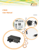
STD35 User Manual Revision 2.
Important information This technical description contains important information to start up and use the STD35 device. Read it carefully before you start working with the STD35. The warranty will be void should damage occur to the device due to non-compliance with these instructions. We cannot accept any responsibility for any loss resulting from this non-compliant use.
If a description for a private end-customer does not clearly state which electric data is valid for a component or a module, how to wire the device, which external components, or additional devices can be connected or which parameters these components are allowed to have, a specialist must be contacted. Devices which operate with greater than 35 Volts have to be connected by a specialist. Before putting the device into operation it should be checked that there is no current leakage on the housing.
Table of Contents Important information ...................................................................................................................................................... 2 Safety Instructions ............................................................................................................................................................ 2 1 Introduction ............................................................................................................................
Overview of Tables Table 1: Available Connectors........................................................................................................................................... 9 Table 2: Configuration Commands ................................................................................................................................. 12 Table 3: Inputs & Outputs commands ..........................................................................................................................
1 Introduction Thank you very much for purchasing our CEP STD35 telemetry device! The STD35 offers the user the possibility to remotely switch ON or OFF electronic devices and to receive alarm messages via (SMS). You can switch devices either with an SMS or using a simple voice call. Alarm messages (SMS) can be received with any mobile phone supporting SMS functionality. With the new generation of the STD35 you now also have the possibility to receive alarm messages via E-Mail.
2 Background Information 2.1 GSM-Network in general The GSM Network (Global System for Mobile Communications) is a standard for all-digital mobile phone networks. Originally GSM has been designed for voice calls, the transmission of text messages (SMS) and the transmission of data with a constant data speed. With the success of the InternetInternet, the GSM network was expanded to offer packet oriented data transmission (e.g.
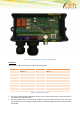
3 Operating Conditions Operate the STD35 only with a supply voltage between 7-32V DC and have in mind the polarity! (see picture1) Use a stabilized power supply with minimum 1A output current. (We recommend using only the original CEP power supply). If you use a mains adapter for power supply it has to conform to the VDE regulations. 4 Loads connected to the device are not allowed to exceed 30 W per relay.
Figure 1: Positioning of the connectors on the STD35 Connectors As described in Figure 1 the STD35 has 5 Green Screw terminals. Outputs (Blue) Inputs (Purple) 1 Output 1 a 1 Input 1 + 2 Output1 b 2 Input 2 + 3 Output 2 a 3 Input 3 + 4 Output 2 b 4 Input 1-5 GND 5 Output 3 a 5 Input 4 (AIN1) + 6 Output 4 a 6 Input 5 (AIN2) + 7 Output 5 a 8 Output 3/4/5 b Table 1: Available Connectors The first two terminal blocks (highlighted in blue) are the output terminals.
Pins 5 and 6 of the fifth row of terminals correspond to the the analogue inputs AIN 1 (Input 4) and AIN2 (Input 5). They share a common ground with the Inputs 1-3 (Pin 4 terminal row three) The voltage supply is applied on pin 1 (VIN +) and pin 2 (GND) of the fourth row of terminals (marked in red). The maximum cross-section of the cables to be screwed into the screw terminals is 0,08 mm² - 1.3 mm² (both single core and multistring).
6.2 Hardware preparations Please insert the SIM card into the SIM card holder on the PCB prior to connecting the supply voltage and switching on the STD35 . To open the SIM card holder move it sideways and flip it open; insert the card (mind the proper orientation of the card) and close it again. Move the top sideways in the opposite direction to lock the SIM card in place. Now please connect the GSM antenna which is part of the delivery to the proper antenna connector on the STD35 board.
7.
Inputs & Outputs commands O4:xxxxx defines time period for relay 4 action (in seconds) 0 = infinite O5:xxxxx defines time period for relay 5 action (in seconds) 0 = infinite A1:xxxxx defines delay for relay 1 reply (in seconds) 0 = no message A2:xxxxx defines delay for relay 2 reply (in seconds) 0 = no message A3:xxxxx defines delay for relay 3 reply (in seconds) 0 = no message A4:xxxxx defines delay for relay 4 reply (in seconds) 0 = no message A5:xxxxx defines delay for relay 5 reply (in seco
CLIP commands CL: add clip list number, asterisk symbol (*) is also supported CD: remove clip list number Table 4: CLIP commands DATA commands EMAIL: 1 - enable email feature 0 - disable email feature default is enabled SMTPIP:XXXXX defines SMTP server IPv4 address example SMTPIP:"smtp.aol.com" max length is 32 SMTPPORT: defines SMTP server PORT example SMTPPORT:2121 value must be a number, in range 0..
DATA commands default is empty FROM: defines email sender example FROM:"p.szymczak@cetec.cc" max length is 25 default is empty TO: defines up to 5 email recipients (separated by ";"), each one max 25 characters example TO:"support@cepag.de" max length of field is 129 [(5*25+1)-1] default is empty BODY: General content of the E-Mail which may contain substitutable variables TESTMAIL Dispatched to request a test email Table 5: DATA commands DOTA commands DOTAAPN:Internet.DOTAAPNUSR:"".DOTAAPNPWD:"".
The following table describes the available variables and the data they represent Variable Description $CALID$ last incoming CLIP number $CNT$ X/Y (where X is sent SMS counter and Y is sent EMAIL counter) $IN1$, $IN2$, $IN3$, $IN4$, $IN5$ current input value as a string (LOW or HIGH) $OUT1$, $OUT2$, $OUT3$, $OUT4$, $OUT5$ current relay value as a string (ON or OFF) $IN1T$, $IN5T$ $IN4T$, current input value as a integer (0 or 1) $OUT3T$, current relay value as a integer (0 or 1) $IN2T$, $IN
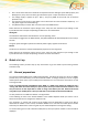
Parameters for representing seconds (e.g. command “O1:xxxxx.”) can have 1-5 digits. Valid parameters are e.g. 1 (for 1 second), 90 (for 90 seconds) or 99999 for (99999 seconds). No leading “zeros” have to be added. Example: “O1:110” stands for 110 seconds. Please observe the difference between the figure ‘0’ and the letter ‘O’!. (“O1ON.” Contains twice the letter O; “V1:0.” contains once the figure 0) 7.
With the command “PN:<4digit password>.” the password can be changed. The password can include letters and figures but special characters are not allowed. All letters have to be in capital. The standard password (factory setting) is 9851. The texts of the event or start-up SMS can be changed with the commands “E1:.”, “E2:.”… and “PT:.”. The message length must not exceed 64 characters. Do not use command syntax inside a message text. The ‘.
8 E-Mail functionality via GPRS Netzbetreiber z.B Vodafone Internet SMTP E-Mail Server z.B. AOL IP Port Benutzername Passwort APN Benutzername Passwort STD32 Figure 2: E-Mail functionality via GPRS The STD35 offers you the possibility to get messages vian SMS and via E-Mail. 8.1 Configuration of the E-Mail functionality Email functionality should work by default if the user has correctly configured the APN settings and the receiver email address.
9 Troubleshooting Problem Possible Reason Solution GSM LED stays dark GSM LED blinks twice cyclically No supply voltageNo SIM card / Improper contact with SIM card Connect power supply Insert SIM card properly or carefully clean contact area of SIM card GSM LED blinks thrice cyclically PIN is not “0000” or “2468” GSM LED constantly on No GSM network available / no antenna connected Change SIM card’s PIN to “0000” or “2468” Connect antenna / Change antenna position GSM LED dies after 3 minutes N
11 Technical data GSM: Quad Band EGSM 850/900/1800/1900 MHz Compatible with ETSI GSM Phase 2+ Standard Output power: Class 4 (2W @ 850/900 MHz) Class 1 (1W @ 1800/1900 MHz) Temperature range: -30°C - +75°C Weight approx. 220 grams Dimensions: 150x65x45 mm (l x w x h) Supply voltage: 7-32V Idle current:34mA, peak up to 1A Max. output current Output 1&2: 5A Max. output voltage Output 1&2: 30V DC; 250V AC Max. output current Output 3&4 and 5: 30V DC Max.
12 Document history Revision Datum Changes Rev. 1.0 16th Dec 2010 Original file Rev.1.1 14th Jan 2011 Update Rev 1.2 23rd Jan 2011 Added Configuration Tool Rev 1.3 6th June 2011 Minor Corrections Rev 1.4 9th June 2011 Corrected relay voltage mistake Rev 1.5 10th December 2013 Change from Telic to CEP, Complete Update Rev. 2.