
Instruction manual


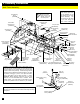
6. Assembly Instructions
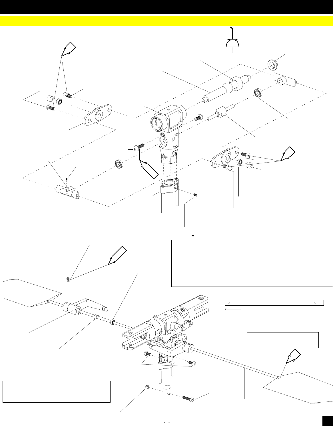
Head Block
Button Head M3X6
(CNM3X6BH)
Linkage Ball
(CNLR1014)
Seesaw Offset Plate
(CNE519A)
CNC Seesaw
(CNE564S)
Bearing 3X10x4
(CNBB1030)
Button Head M3X6
(CNM3X6BH)
Seesaw Offset
Plate
(CNE519A)
Button Head M3X6
(CNM3X6BH)
Linkage Ball
(CNLR1014)
Bearing 3X10x4
(CNBB1030)
Seesaw Shaft
(CNE518)
Feathering Shaft
(CNE521A)
Rubber Dampener
(CNE520)
Blade Grip Spacer
(CNE522)
Set Screw M4x4
(CNM4x4SS)
Bearing 3X7x3
(CNBB0730)
*Apply small amount of CA to
the threads of the ybar
CNC Flybar Control
Arm (CNE559A)
Flybar
(HW3173A)
Flybar Paddles
(HI3179)
Spacer M4X6x3
(CNE559A)
Measure the ybar evenly on both sides. Measure from the ybar
control arm to the tip of the ybar prior to installing the ybar paddles.
Screw the paddles evenly on both sides of the ybar.
After attaching the paddles, measure the inner side of the ybar to
the tip of the y bar control arm, and verify that the ybar is equal on
both sides.
Hint: Note the orientation of the ybar con-
trol arm the ball link faces the angle off at-
tack and the set screws faces upwards.
CA
OIL
CA
CA
THREAD LOCK
B
Head Block
(CNE556-1)
Spacer M4X6x3
(CNE559A)
Set Screw M3X3
(CNM3X3 SS)
CNC Washout Guide
(CNE556-2)
THREAD LOCK
B
Ball Bearing 4x8x3
(CNBB48)
CNC Seesaw
Spacer
(CNE564S)
M3X3 Set Screw
Button Head
M3X6
(CNM3X6BH)
7
Cap Screw M3X22
(CNM3X22CS)
M3 Lock Nut
Main Shaft
Shorter distance between hole
and end towards head block