
Instruction manual


6. Assembly Instructions
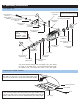
Head Block
Washout Pin M35x2
(CNE517)
Button Head M3x6
(CNM3x6BH)
Linkage Ball
(CNLR1014)
Seesaw Offset Plate
(CNE519)
Tie Bar
(CNE519)
Bearing 3x10x4
(CNBB1030)
Button Head M3x6
(CNM3x6BH)
Button Head M3x6
(CNM3x6BH)
Seesaw Offset Plate
(CNE519)
Button Head M3x6
(CNM3x6BH)
Linkage Ball
(CNLR1014)
Bearing 3x10x4
(CNBB1030)
Seesaw Shaft
(CNE518)
Tie Bar
(CNE519)
Feathering Shaft
(CNE521)
Rubber Dampener
(CNE520)
Brass Spacer M8x7x3
(CNE522)
Dry fi t the pins prior to ap-
plying Ca. Use medium CA
to allow slower drying time to
press into place.
Set Screw M4x4
(CNM4x4SS)
Bearing 3x7x3
(CNBB0730)
*Apply small amount of CA to
the threads of the fl ybar
Flybar Control Arm
(CNE525)
Flybar (CNE526)
Flybar Paddles
(CNE527)
Plastic Spacer M3x6x3
(CNE525)
Measure the fl ybar evenly on both sides. Measure
from the seesaw arm to the tip of the fl ybar prior
to installing the fl ybar paddles. Screw the paddles
evenly to both sides of the fl ybar
Measure inner side of the fl ybar to the tip of the fl y
bar control arm, and verify that the fl ybar is equal
on both sides.
Hint: Note the orientation of the fl ybar con-
trol arm the ball link faces the angle off at-
tack and the set screws faces upwards.
CA
OIL
CA
CA
CA
THREAD LOCK
B
Head Block
(CNE517)
7.