
Instruction manual


Final Adjustments - Radio Setup
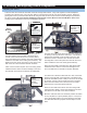
10. Setup and Adjustment
Now that the servo installation into the helicopter is fi nished the following pages should be reviewed. As various types of radios
can be used to setup the helicopter, some of the following information may not apply.
Servo Direction (Servo Reversing)
Check that all servos move in the correct directions.
Dual Rates
For beginners (using fl ybar weights, or optional beginner pad-
dles Part #HI3179) the dual rate values should be set at 100%
for both switch positions until hovering has been mastered.
Normal position: (high rate) 100%
Switch position 1: (low rate) 75%
Exponential
The exponential function allows adjustment of how sensitive
the cyclic controls are when the machine is hovering. This
should be left at 0% (linear) until all trimming is complete.
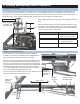
Sub Trims
The sub trims on the outside of your transmitter are used to
fi ne tune the servo center positions while testing or in-fl ight. If
the trim has to be moved more than 2-3 divisions then readjust
the linkage length to set the trim back in the center.
Travel Adjustment ( endpoints )
Using endpoints to adjust to the limits of how far the servo is
allowed to move is very convenient for fast set-up. If binding
occurs simply reduce the travel in that direction. ** Note: by
changing one side only (high or low stick) the servo travel is
no longer linear which will tend to make that control surface
unstable. It is better to set the high/low adjustments the same,
or make actual pushrod adjustments.
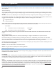
Flight
Mode
Setup Method Low Pitch
(Low Stick)
Hovering
(Mid Stick)
High Pitch
(High Stick)
N Beginner 0 5 9
N Hovering -2 5.5 9
1 Stunt & Aero-
batics
-10 5.5 9
2 3D** -10 0 10
H Auto-rotation -10 5 11
Pitch Curve Values by Degrees
Pitch & Throttle Curve Adjustments
The ultimate goal for adjusting the curves on your helicopter
is to reduce how much the tail rotor moves during fl ight and
aerobatics. This leads to maintaining a consistent main rotor
RPM which can only be achieved through adjusting the indi-
vidual values which control the pitch and throttle at a given
stick position.
Pitch Curve Adjustment
The following chart shows the values for the collective pitch
measured in degrees which are made on the helicopter using
a pitch gauge. The Travel Adjustment function (if available
makes these settings easy).
For the beginner it is recommended to set the low stick
position to 0 degrees to avoid damaging the helicopter while
reducing the power during the fi rst few fl ights. These set-
tings will need slight adjustments to keep the helicopter at a
consistent height at mid stick.
( N - Normal fl ight mode, 1 - Stunt mode one, 2 - Stunt mode two,
H - Throttle hold-autorotation )
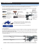
Final Adjustments - Tail Rotor Setup
What separates airplane radio equipment from the helicopter version is in the control of the individual curves discussed earlier
and in the Revo-mixing*.
Take a moment to consider the helicopter hovering in front of you.
Problem: Not enough pitch in
tail rotor to match torque set-
ting of motor.
Action: Increase pitch by
shortening the rudder push-
rod.
1
Nose rotates left at hover
Problem: Too much pitch in
tail rotor to match torque set-
ting of motor.
Action: Decrease pitch by
lengthening the rudder push-
rod.
2
Nose rotates right at hover
21.