
Instruction manual

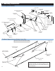

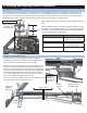


(1) Each rotor blade has 3 holes drilled in the root. Use epoxy to glue the plastic root ends to the exposed wood pre-cut by
the factory. Use the countersunk screws to secure the root ends to the blades and let the glue dry.
(2) Use the 2 M4x30 blade bolts and M4 locknuts to secure the blades to the blade grips on the main rotor head. Main
rotor blades should have their leading edge turning clockwise.
IMPORTANT NOTE: MAIN BLADES AND FLYBAR PADDLES TURN CLOCKWISE.
Trailing edge
Leading edge
M2.5 Countersunk
blade root screws (4)
Blade bolt
hole with
spacer
IMPORTANT
NOTE: MAIN
BLADES
AND FLYBAR
PADDLES TURN
CLOCKWISE.
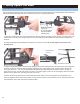
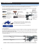
Tracking Adjustment
(3) Tracking refers to trimming the actual pitch of the main rotor blades to be equal. On the fi rst fl ight, bring the rotor head
up to speed without leaving the ground and look at the side or profi le of the rotor disk (FROM A VERY SAFE DISTANCE,
MAKING SURE TO WEAR EYE PROTECTION).
(4) Only one rotor blade should be visible, if there are two distinctive blades then the tracking linkage must be changed.
Observe which blade is tracking above the other by marking one fi rst. Track that blade lower by shortening the ‘bell mixer
to swashplate’ linkage rod.
Very Bad!
Improved!
Trailing edge
Leading edge
ASSEMBLY COMPLETE! MODELER IS RESPONSIBLE FOR COMPLETENESS AND SAFETY OF THE MODEL.
Bell mixer to
Swashplate
linkage
M4x30 Shouldered
Socket Head Cap
Screw (2)
M4 Locknut (2)
Blade bolt spacer
(not used)
Blade root cover
Blade root cover
Apply thin CA
glue to attach
blade root covers
to blades
Preparing, Mounting & Tracking The Main Rotor Blades
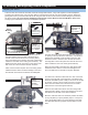
9. Final Preparations
Balance is the most important part in maintaining a safe
and reliable helicopter. First check the blades for balance,
this can be done on a blade balancer.
(Optional Item) CN2052 Accuratech Main Blade Balancer.
20.