
Instruction manual

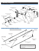

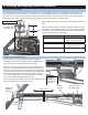


Linkage:
bell mixer to
swashplate
(2) = 100mm
Linkage: fl ybar
control arm to
washout arm
(2) = 54mm
Linkage: bell
mixer to seesaw
(2) = 25mm
Linkage: Aileron/
Pitch control arm
to swashplate
(2) = 78mm
Linkage:
Elevator Servo
to swashplate
(1) = 50mm
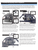
1) Before proceeding to measure and install the
pushrods, make sure you have adjusted the
fl ybar to it’s optimal level. Adjust the fl ybar until
the outer fl at spots align with the set screws
in the fl ybar control arms (set screws facing
upward and fl ybar control arms are fl ush up
against the seesaw).
2) Make certain that the fl ybar is equal in length
on both sides of the rotor head before tighten-
ing the fl ybar control arms. Set the fl ybar control
arms fl ush and level to the seesaw and tighten
the set screws using locktite.
It is very important that before you install the
pushrod linkages that you fi rst charge your
radio then remove all the servo horns from the
servos and center all the mechanical or elec-
tronic trims on the radio.
Due to the different types of radio and servos
that are chosen to install into the helicopter,
match each pushrod to the lengths in the table
for optimum setup.
Note: All dimensions are in millimeters and
are measured from the centers of the con-
trol balls or ball ends.
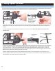
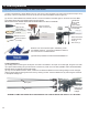
7. Putting Together Your Model
Servo Linkage Lengths
Location Length ID
Aileron/Pitch Control Arm to Swashplate 78mm A
Swashplate to Bell Mixer Link 100mm B
Bell Mixer to Seesaw 25mm C
Elevator Servo Linkage to Swashplate 50mm D
Flybar Control Arm Linkage to Washout Arm 54mm E
A
A
B
C
D
E
These lengths should allow for approximately +/- 10 degress of pitch
with 0 degrees at center stick (typical 3D setup).
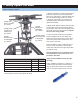
(Optional Part) CN2255 Control Rod Set-
up Gauge
Easily duplicates pushrods by attaching a
master pushrod and match new pushrods as
they are assembled. Gauge has millimeter
scale for accurate lengths center to center.
15.