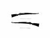
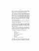
Right SIDS view of tne F. N. orifice {Mauser System) Loft side view of the F. N rifle {Mauser Systole.
Description of the F. N. Rifle Mauser System) The rifle 13 composed of tha following main parks: . The barrel with front and rear sight, . The locking-and firing mechanism. . The repeating mechanism. . The slick with hand guard. . The fittings, . The bayonet. 1. -~ THE BARREL has a length of 58% m/m. {or 740 m/m) and its reinforced rear end is screwed lino the body. The fling is right handed and consists of four helical grooves.
-5 pawls, the taller engage under the effect of the pawl springs in the corresponding notches of the tangent. The tom gent is secured to the bed by means of 2 small lateral bearings which rest on the hinge. A pin running through the leaf cmd fastened to the hinge prevents losing the tangent in cutie the spring should break, Om the front end of the barrel s soldered the fore sight ring and block which form the support of the fore sight.
bridge is the opening tor the bolt sip and the ejector whilst a groove provided with o ramp is arranged in the bottom of this part of the body fo receive the safety lug of the bolt. The blat stop and the ejector are both fastened at the left side of the bridge of the body by means of the same pivot screw. The bolt stop has a catch projecting into the interior of the body. The left lug of the bolt comes into contact with the catch when the bolt is entirely drawn back.
—7 locking lugs provided with chambered edges which facilitate the locking of the rifle; the left lug is split in order fo allow of the passage of the ejector, A semicircular groove let into the bolt head and provided with a small romp serves as o goods for the extractor.
—8 grasp a cartridge put by hand into the chamber. lis slightly curved form allows of its ac ing as a spring ensuring in this way its proper fastening upon the bolt, THE FIRING PIN AND ITS SPRING.
G THE SAFETY DEVICE consists of the safety teal and the safety spindle which are rigidly connected. This spindle is notched in such a way that the smooth portion, according to the position in which it is pul, occupies or not the safety notch of the bolt, lacking thew the bolt plug or disengaging it from the latter.
— The magazine spring connects the cover plate of the magazine with the platform fo which it is secured by 2 bearings. The platform is shaped to ensure the correct feeding of the cartridge at the moment of entering into the chamber and facilitates this movement. The magazine can hold 5 cartridges placed in zigzag fashion. The sides of the magazine are formed by the trigger ward which further consists of the finger guard, the recesses of the locking screws of the finger guard and their check screws.
THE FITTINGS consist of the cleaning rod. I screws into & nut let into the stock.
Dismantling and Reassembling DISMOUNTING. 1~ Unscrew and remove the cleaning rod. 2° Remove the sling. 3" Remove the bolt and dismantle same. Cock firing pin and raise the safely wing in the intermediate position between the salty position and the firing position. Remove the obit from the breech by pressing aside the boll stop with the left thumb.
—3 = Disarming the finalist meteor ism Push the extractor leeward. The exterior is separated kom the bolt when the 2 small lugs of the trouble ring disengage from their seats beneath the extractor. 4 To remove the magazine cover plate, spring and piscatorial. — No special col is required.
— i — can be easily removed by pressing the point of a cartridge in the catch which ig just in front of the trigger guard and pushing 1t towards the trigger ward. Draw out the magazine cover plate, the magazine spring and platform. Separate the different pairs by removing the spring leaves from their bearings in the platform and in the magazine cover plate. 5 To remove the upper and the lows bend.
e 15 To strip the trigger mechanism, drive out the axis pin of the trigger bar in order 1o set free the trigger bar, the trigger and the trigger spring, the trigger pin, being riveted, must not be removed. Unscrew the nut of the cross piece and take out the latter. H Remove the pin of the cover pale catch, thus sating free the taller part and iis spring. REASSEMBLING. 1¢ To reassemble the bolt stop, the ejector, the sight tangent end the rigger mechanical. . If necessary.
replace tha upper and the lower band. — Puce the lower band in such a way that it 15 again retained by its spring. Mount the upper band, making sure that it enters into the COSSET. 5 To replace the magazine cover plies. the spring and the platform.
— Assemblage the ext racier When the belt is being inserted the body. care must be taken that the extractor stands in the correct position over the right hand lug and the wing of the safety hilt to the left. 7> Replace the sling.
Manipulation and working Opening the Breach. — Grip the rifle with the left hand between the rear sight and bolt and let het hand remain thees during all loading movements. The right hand grips the bolt lever, turns it upward on eight of & turn and then pulls it back until it stops against the bolt stop.
— 18 held by the lip of the breech and ifs base is placed in front of the face of the bolt. The clip is left in 1he vertical groove of the bridge. Closing the breech. The right hand again grips the bolt ever, the finger nails being turned fo the left ; the bolt is pushed fully heme cnd the lever turned to the right. As the bolt moves forward, it encounters the lower end of the clip and throws it out.
— 20— Disengaging the safety. Turn the sally to the left. When the non notched portion of the spindle is withdrawn from the safety slot in the bolt, the obit is no longer locked ; the cocking piece advances until the stud engages with the sear. Firing. Under the effect of ths spring of the rigger bar, the sear nose projects into the groove of the ilia of the body, the trigger rests on its front cam underneath the body and is connected to the rigger bar by its pin. Press the tail of the trigger backwards.
2] To place the cartridge on the clip. Engage the groove of the cartridge case in the lips of the clip; the cartridges are retained on the clip by means of the clip spring. F. N.
General data Calibrate t Twit. #88m/m| 78 m/m Length of rifle without bayonet] 1.088m. {1,099 m. [1.099m. Length of rifle with bayonet .| 1479 m.{ 1479 m. {1478 m, Weight ol rifle without bayonet {app) . . 3.875 kgs. 3.875 kas. 1 B75 ks, Weight of rifle with colonelcy 4.350 kgs 3.350 kas Length of blame m {589 m/m Length of line of sight . . .
F. N. Repeating Carbine {Mauser System} The construction of the F. N. carbine (Mauser system) is based on the same principle as the F. N. rifle, buts its length is reduced mn order to nest the requirements of light troops, machine gun and artillery men, as well of those of special bodies of constabulary, frontier wards elc. These troops which are to move quickly over ground of every nature, would be hindered in their movements by an arm of too great length.
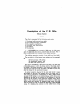
Ballistics of the F. N. Rifle, Cal. 7 m/m Bullet 5. 9 gr. Angle Angle Time of | Height of | Remaining | Remaining Denver tongueless of dispersion | Distance of of fight trajectory | velocity energy Zane OREO o % elevation descent sec. ™ mis g, H=1en70 Weft 8529 3337 — 200 026 0,08 7208 2383 total 7 T8 400 056 0,38 801.