D2 Turbo Pocket mechanical installation guide TM DOMESTIC SLIDING GATE OPERATOR
This guide is designed specifically for installers who are familiar with the installation of standard sliding gate motors, but do not know the specifics of the D2 Turbo. Please do not proceed with the installation until you have read and fully understand the Safety instructions included in your product packaging. The Safety instructions are also available on www.centsys.co.za, and may also be obtained by contacting Centurion Systems on +27 860 236 887 (SA only).
8 7 6 8 3 2 5 1 4 Legend 1. 10V - 24V AC or 10V - 28V DC supply cable via step-down transformer (mounted in house/dwelling) (2 core cabtyre or twinflex, thickness depending on distance of cable run and transformer output voltage. Refer to Cable Thickness Table in the User Guide Optional wiring (all cable is multi-stranded): 2. Intercom cable from motor to dwelling (n1 + 6 core 0 .5mm2) 3. Intercom cable from motor to entry panel (n2 0.5mm2) 4. Safe CLS: Recommended infrared safety beams (3 core 0.
Mounting studs 8B.2. Fit the mounting studs to the foundation plate and secure in place with the stud locknuts. Stud locknut (M10 half-height nut) Foundation plate Level this end of the rack, and fix 8B.3. Position the foundation plate to allow for the pinion to be unmeshed from the rack when the gearbox has to be removed. Leave clearance under the gearbox to allow for the gearbox to be lowered if the rack and pinion mesh is too tight.
The pinion guard is easily removed and rotated allowing the rack to be fitted above or below the pinion. 8B.5. Use the orange heightadjustment nuts provided to level the gearbox. 8B.6. Tighten the hold-down nuts when the gearbox is in the correct position. Holddown nuts (M10 nuts) Orange heightadjustment nuts Washer Stud locknut (M10 half-height nut) Discus padlock Theft-resistant nut and Discus padlock are available from CENTURION for sites requiring additional security.
9.1. Always check that the circuit breaker in the electrical panel is in the OFF position, and that all high voltage circuits (more than 42.4V) are completely isolated from the mains supply before doing any work. 9.2. Ensure that all low voltage systems (less than 42.4V) are suitably protected from damage, by disconnecting all sources of power such as chargers and batteries before doing any work. 9.3.
PFA: The Pillar Light relay will activate for two seconds before gate movement occurs, as well as during gate movement.
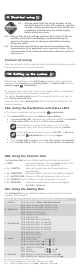
110 - 220V Mains in CP106 Relay Card E N L i5 Infrared safety optional, but beam (opening) recommended optional Connection type: Normally closed To alarm panel, etc Relay card CP106 Rx NO Tx NC COM Waterproof isolator enclosure within two metres of motor IRB Receiver SETUP: TES MO RE B 12V+ 12V- 12V- AUTOC LO SE C Aux 12V Safe Com Com PROF ILE E Step 1: Select FUNCTION Step 2: Select SETTING Step 3: Press Step 4: When finished select RUN DE MO D 110-220V E N L 12V+ COM NC optio
Sharecall 0860-CENTURION (0860 236 887) Head Office: +27 11 699 2400 Sharecall Technical Support 0861 003 123 or +27 11 699 2481 from 07h00 to 18h00 (GMT+2) (Sharecall numbers applicable when dialed from within South Africa only) 0.07.A.0095_05022014 www.centsys.